215.4(A) 4W Riser serving 3W Apartments

Status
Not open for further replies.

MyCleveland

Senior Member
Location
Cleveland, Ohio
I touched on this issue in an earlier post along with other issues related to this design method back in Oct.

http://forums.mikeholt.com/showthread.php?t=179824

Spanked thoroughly, but would like to resurrect discussion on this specific article.

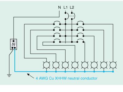
The basic design scheme...multi-family 120/208v-3p-4w service with each apartment served 3W, nothing new here.
Design provides for 4W risers to serve 3, 4, 5 or six apartment. NEC does not cap the number, these are numbers from plans I have seen installed.
Each apartment is served via 3W tap from the 4W riser. Metering achieved electronically (CT's).

The push back was that this article would not apply because the riser is a 4W feeder, and each tap is a separate feeder and therefore NO sharing of a common neutral.
My claim was the neutral could be simply looped up the riser, source - pnl - pnl - etc and this would help visualize these feeders are in fact sharing a common neutral.
I have recently ran multiple electronic circuit models of both designs with identical loads and in every case the neutral current along the neutral for each design is the same +/- .5amp as compared to a design of separate phase conductors, six sets...a-b, b-c, c-a, etc + common neutral up the riser.
The point being if the writers intention is to put limitations on this design method, I am assuming because of specifically the potential to overload the neutral.

Help me get this out of my head.
 
Its important to note:

1. When 2 phases off a 3 phase system are used the neutral current is equal to the phase current assuming both phases are equal in load. Phase current equaling N current is the worse case scenario for linear loads.

2. NEC calculated loads are always higher than the actual load.


Hope I am on the right course. :angel:
 
Neutral current equaling line current, could not come up with an apartment design where this could happen.
Vector addition of both apartment L-N currents never added to a large value because of the phase angle separation.
Try a few.
 
Neutral current equaling line current, could not come up with an apartment design where this could happen.
Vector addition of both apartment L-N currents never added to a large value because of the phase angle separation.
Try a few.

It will one a 3 wire feeder. 40 amps one leg one 40 amps on leg two equals 40 amps one the noodle.
 
I
The point being if the writers intention is to put limitations on this design method, I am assuming because of specifically the potential to overload the neutral.

Help me get this out of my head.

This is not a common neutral.

The restriction is about running one large neutral for multiple feeders.

Your installtion is fine.
 
Here is an example from the NEC handbook that shows what a 'common neutral' is to the NEC.

In this case a common neutral for multiple branch circuits.

commonneutral.JPG
 
Iwire...thanks for the schematic, year and page this came from ?
My discussion is on 4W, so your distribution main would be 3P OCPD....everything else is same except my model used six apartments.
Statement "This is not a common Neutral", Ran this issue by two doctorates, It is a common neutral.

I ran the models to convince myself the N currents along the riser....both designs are the same.
 
Iwire...thanks for the schematic, year and page this came from ?

Maybe 2002 it has to do with 225.7 but it is an example of what the NEC means 'common neutral' notice the neutral in that circuit is common to all the circuits not just one or two of them.

My discussion is on 4W, so your distribution main would be 3P OCPD....everything else is same except my model used six apartments.
Statement "This is not a common Neutral", Ran this issue by two doctorates, It is a common neutral.

The installation you have described above in this thread and in your other thread does not use a common neutral.

It is one feeder and one feeder only

215.4 does not apply to your installation.


I ran the models to convince myself the N currents along the riser....both designs are the same.

There are no models to run, you are wasting your time. 215.4 has nothing to do with your proposed job.
 
Iwire

I get what you are saying regarding NEC interpretation.
If the result of the design (cct analysis) yields the same result, then the 4W riser concept is the same as your diagram.
Only diagrammatic difference is the 4W riser is simply extending the bus and each tap in fact shares the same neutral.
 
Just to clarify Bob's graphic was provided only to illustrate a definition. That arrangement is only permitted for installations under Article 225 which would be outdoors for something like site lighting.
 
Just to clarify Bob's graphic was provided only to illustrate a definition. That arrangement is only permitted for installations under Article 225 which would be outdoors for something like site lighting.

Yes and no.

It is apparently also allowed to some extent with feeders as well.

In the case of 3 phase 4 wire feeders it seems one common neutral could be run for up to two sets of feeders. Two feeder breakers supplying a total of six ungrounded and using one common grounded conductor.

Why would I do this? I would not but that seems to be what 215.4(A) is allowing or limiting depending on your POV.
 
Yes and no.

It is apparently also allowed to some extent with feeders as well.

In the case of 3 phase 4 wire feeders it seems one common neutral could be run for up to two sets of feeders. Two feeder breakers supplying a total of six ungrounded and using one common grounded conductor.

You're correct but that's not what is depicted in the graphic. :)
 
Trying to keep on point here...
Iwires schematic vs 4W riser serving each of the 3W loads.
The neutrals in both cases are subject to the same currents as collected along riser.
Both designs are sharing a common neutral.

You can parse up the 4W riser into a feeder, and call each of the taps a 3W Feeder Tap and treat as individual components.
End result regarding the neutral is the same for both cases.

I don't know the history or origin of 215.4(A), but the reasoning I can assume is a concern for overloading the neutral.
If it invalidates one concept, it should do the same for the 4W because the conditions on the neutral are the same.
 
I don't know the history or origin of 215.4(A), but the reasoning I can assume is a concern for overloading the neutral.
If it invalidates one concept, it should do the same for the 4W because the conditions on the neutral are the same.
The reason was somebody didn't like that there was no prohibition on running a "common" neutral and made a proposal for a code change, nothing other than that. There was no worry given at all about overloading. Neutrals have always been required to be sized to carry their load as long as I have been alive.
 
The text is only there because someone said please....really.

People have tried to help you

You refuse to listen or even try to understand. Good luck.

215.4 has nothing to do with preventing neutral overloads, when you use a common neutral like that it has to be sized for the load.

You DONT HAVE A COMMON NEUTRAL, what you have is a common wiring method that you clearly do not understand.
 
Trying to keep on point here...
Iwires schematic vs 4W riser serving each of the 3W loads.
The neutrals in both cases are subject to the same currents as collected along riser.
Both designs are sharing a common neutral.

You can parse up the 4W riser into a feeder, and call each of the taps a 3W Feeder Tap and treat as individual components.
End result regarding the neutral is the same for both cases.

I don't know the history or origin of 215.4(A), but the reasoning I can assume is a concern for overloading the neutral.
If it invalidates one concept, it should do the same for the 4W because the conditions on the neutral are the same.


If that was the case, then why did they not outlaw multi wire branch circuits?
 
Status
Not open for further replies.
Top