25 OHMS RESISTANCE

Status
Not open for further replies.

don_resqcapt19

Moderator
Staff member
Location
Illinois
Occupation
retired electrician
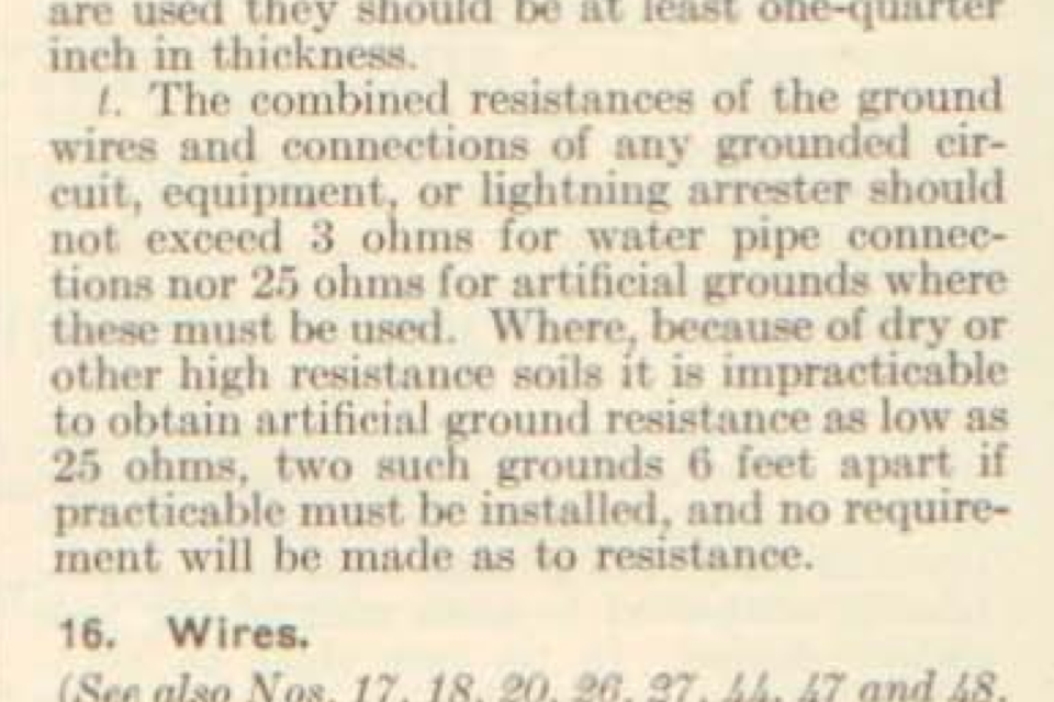
While it is true that it is easier to drive two rods, what is the reason behind this requirement of the code of 25 ohms? Why then would the code allow 2 driven rods that will higher than 25 ohms and not allow one driven rod which may be a little bit higher than 25 ohms?

What is the intent of the code for this 25 ohms? Any scientific basis?

Like a lot of things in the code, it is nothing more than an arbitrary number.
 

dereckbc

Moderator
Staff member
Location
Plano, TX
what is the reason behind this requirement of the code of 25 ohms? Why then would the code allow 2 driven rods that will higher than 25 ohms and not allow one driven rod which may be a little bit higher than 25 ohms?

What is the intent of the code for this 25 ohms?

Like I have said many times it is an antiquated requirement added to the 1918 code cycle (I think, don't hold me to that code cycle). Again from my research it comes either from Telegraph systems of the 1800's, or from Edison in the 1800's. Take your pick

When Edison built the first distribution system he used only 1 conductor and used Earth for the return conductor. 25-ohm happened to be about the same impedance of the phase conductor of a #8 AWG ran 7 miles. The 25-ohm requirement seems to be the highest acceptable impedance that would guarantee Edison?s system to work.

The other plausible answer is it came from Cromwell Fleetwood Varley. Mr Varley was one of the first developer of the British Telegraph system. Some time in the 1860's he was summoned to the USA to help resolve problems with Western Union telegraph that plagued the company operations. Like Edison first distribution system Telegraph systems used only 1 conductor, and earth as a return conductor. Varley found ground resistance to be the problem and recommended ground resistance should be 25 Ohms or less.

Regardless of which one, Edison, Varley, or other unknown party as the originator of the 25 ohm requirement is irrelevant because in low voltage (NEC applications) earth cannot be used as a conductor so the requirement is antiquated. Electric utilities are the only ones who can use earth as a conductor, and it can only be done with high voltage systems.
 

gar

Senior Member
Location
Ann Arbor, Michigan
Occupation
EE
140412-2445 EDT

dereckbc:

No way did Edison depend upon earth as one of his conductors. Just consider the impossibility of adding 25 ohms in series with his system load. His 1879 generators (dynamos) were about 5 kW capacity at about 110 V. A 25 ohm load at 110 V is 4.4 A, or a power of 484 W. That is about 1/10 the capability of the generator.

Edison fully realized that to build a useful electrical distribution system that it was necessary to make the internal resistance of the generator and the distribution system low enough that the loads on the system could be randomly turned on and off without a large voltage change at the load. For the Pearl Street Station this would mean very large conductors. In fact the three wire distribution system (the creation of a neutral conductor) was invented to reduce the amount of copper used.

http://en.wikipedia.org/wiki/Pearl_Street_Station 175 HP input with electrical output of possibly 100 kW. Started as one generator.
http://www.coned.com/history/electricity.asp Confirms the 100 kW figure.

110 V at 100 kW is 909 A, and we can expect the total source resistance at possibly less than 1/10 this load, but not one cable. Rsource = about 110/(10*1000) = 0.011 ohms for the total loop. Nothing close to 25 ohms.

.
 

kwired

Electron manager
Location
NE Nebraska
140412-2445 EDT

dereckbc:

No way did Edison depend upon earth as one of his conductors. Just consider the impossibility of adding 25 ohms in series with his system load. His 1879 generators (dynamos) were about 5 kW capacity at about 110 V. A 25 ohm load at 110 V is 4.4 A, or a power of 484 W. That is about 1/10 the capability of the generator.

Edison fully realized that to build a useful electrical distribution system that it was necessary to make the internal resistance of the generator and the distribution system low enough that the loads on the system could be randomly turned on and off without a large voltage change at the load. For the Pearl Street Station this would mean very large conductors. In fact the three wire distribution system (the creation of a neutral conductor) was invented to reduce the amount of copper used.

http://en.wikipedia.org/wiki/Pearl_Street_Station 175 HP input with electrical output of possibly 100 kW. Started as one generator.
http://www.coned.com/history/electricity.asp Confirms the 100 kW figure.

110 V at 100 kW is 909 A, and we can expect the total source resistance at possibly less than 1/10 this load, but not one cable. Rsource = about 110/(10*1000) = 0.011 ohms for the total loop. Nothing close to 25 ohms.

.
I was thinking no way myself, but not exactly the same things you mentioned, but rather the simple fact that if you insert a 25 ohm resistance that is not the desired load to be operated in a 110 volt circuit, you will certainly see much less then 110 volts at the desired load. The resistance of the desired load will determine exactly what you end up with, then if you change the load in any way your voltage will change accordingly.

They only get away with using the earth as a normal current carrying conductors in the medium and high voltage ranges.

Kind of like having a pinched garden hose, you need to increase the pressure to overcome the resistance to get the desired performance out of that hose.
 

dereckbc

Moderator
Staff member
Location
Plano, TX
No way did Edison depend upon earth as one of his conductors.
Not my story and I never said Edison used SWER just repeating what has been said over the years of research. But SWER exist and has existed since the late 1800's along with Telegraph. It is used today in Alaska, New Zealand, and Australia. Take your pick, either SWER, TELEGRAPH, or arbitrary number picked out of the sky. Point is does not matter where it came from, the 25 Ohm verbiage is antiquated and serves no purpose or has any meaning. It is just a Paper Tiger that needs to be eliminated IMO.
 
Last edited:

kingpb

Senior Member
Location
SE USA as far as you can go
Occupation
Engineer, Registered
OK, I heard back from our grounding expert:

The source for the 25 ohms value has never been entirely clear. The 25 ohms does not ensure safety to personnel, or equipment.


Driving the second ground rod does not require testing and if the first rod does not meet the 25 ohms, even though there is no guarantee the addition of the second rod will meet this value either. the ohm value is highly dependent upon the soil. Even the minimum distance of 6? between the rods is not the most efficient use of resources to lower the resistance.


The reasoning behind this 25 ohm value is that it should be able to be reached in most soils in the US, and thus it does not put undue pressure on home owners and commercial/businesses for grounding requirements. Kind of a one size fits all.


However, many Contractors installing these ground rods in this manner will not have the equipment or even the understanding to properly test for the 25 ohm resistance. Improper test procedures can actually give a false reading, either high or low.

For most projects in generation, substations, telecom, and water; the NEC value should not be followed in the sense that achieving 25 ohms is acceptable. A much lower value of 1 ohm or less, tested by appropriate procedures and for proper levels of step and touch potential, and hazard mitigation should be accomplished by trained personnel.


dereckbc

Moderator
Staff member
Location
Plano, TX
For most projects in generation, substations, telecom, and water; the NEC value should not be followed in the sense that achieving 25 ohms is acceptable. A much lower value of 1 ohm or less, tested by appropriate procedures and for proper levels of step and touch potential, and hazard mitigation should be accomplished by trained personnel.
Well I work the Telecom sector now and Generation in my first 10 years. Telecom is traditionally 5 ohms, but today there is no minimum requirement in the telecom sector. Rather proper lightning protection design and isolation techniques to be used. Generation is a different animal as earth is used as a conductor and a fault return path. In a sub-station there is a grid underneath that gravel. Any area where workers can have access to switches, Transformers, Capacitor bank etc will be on a raised steel platform bonded to the grid to minimize step gradient potential. Just like a nearby lightning strike can kill you , same applies in a high voltage sub-station the distance between your feet can kill you.
 

Sparky3141

Member
Location
N/A
Ok, so the number is meaningless. Is the application also meaningless? Nearest I can figure is that the only reason to ground the service is possibly to assist a lightning strike to reach ground as soon as possible to reduce side flashes from starting a fire in a structure. More importantly, where is the measurement taken? Is it at the service grounding electrode completing a circuit back through the grounded service conductor back to the transformer, through its grounding electrode and back to the service grounding electrode? I recently watched a Mike Holt video of him doing this but the Code wording is confusing as to what is supposed to be measured. It's like it is saying to measure the resistance between the electrode and earth; which doesn't make sense to me 'cause if the ground rod is touching earth already... :::shaking head:::
 

gar

Senior Member
Location
Ann Arbor, Michigan
Occupation
EE
140430-2106 EDT

Sparky3141:

The earth is a large hunk of material with a pathway from the surface to the interior for electrons (negative charges) or holes (positive charges) to flow. If you pick some small point on the earth and drive a ground rod into the earth, then you can measure some resistance from the rod to the much larger body of the earth. Treated as a complete body the earth is quite a low resistance, but the entry points to it are not very low.

To conduct energy into the earth from a lightning discharge you want the conductivity into the earth to be as high as possible (low resistance). The more surface area contact with the earth the better. Also whatever the conductors are into the earth these should be wide and thin to lower the high frequency impedance.

For conductors into a home or building you need high impedance paths to high frequencies leading into the building. And interior to the building you do not want paths to earth.

If you had a 10,000 A lightning bolt directly hit a ground rod with a 25 ohm impedance into the earth, then that rod would rise 250,000 V above some place in the earth. Likely there will be electrical breakdown within the earth because the voltage gradient close to the rod will be very high. Thus, the rod won't be 25 ohms during the lightning current.

.
 

kwired

Electron manager
Location
NE Nebraska
Nearest I can figure is that the only reason to ground the service is possibly to assist a lightning strike to reach ground as soon as possible to reduce side flashes from starting a fire in a structure.

I would say that is mostly correct, the grounding electrode primary feature is lightning dissipation. When you figure the high voltage and high frequency involved 25 ohms is not all that high of a resistance to have much negative effect. It is definitely too high of a resistance to do much for the normal operational voltage of 600 volts or below, and maybe even up to 2k to 5k volts, above that grounding electrodes start to carry enough current to be somewhat useful for fault clearing.
 
Status
Not open for further replies.
Top