30 kVA small distribution transformer

Status
Not open for further replies.

alokanant

Member
Location
houston
This questions is with reference to the following thread:

http://forums.mikeholt.com/showthread.php?t=122067&page=2

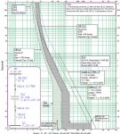
If we follow the NEC tables the maximum overcurrent protection settings can be set. However if we plot the transformer damage curve with the protective devices and the transformer the transformer (esp. the overload or low fault current range) is not protected. This is particularly true for transformers with Delta - Star solidly grounded transformers, for which the transformer damage curve needs to be shifted to the left by 58%.

Is this typical to have, or is there a better way to protect than using molded case thermal magnetic CBs. The transformers under consideration are 30 kVA or 45 kVA, which I guess are not that expensive to replace and possibly in a commercial setting are unlikely to get overloaded, although the possibility of single line to ground fault cannot be ruled out.

Thank you.
 
I am not entirely sure what it is that you are asking.

If you have a short to ground on the secondary it should trip the secondary protection instantly, so where would the damage come from?
 
When he mentions a single line to ground fault, I think he is supposing a high resistance fault which manages to continue "forever", not a bolted fault.
The kind if fault that could create an overload which hides in the area near the 135% mark of a breaker. The sort of "fault" that would end up tripping the overload on a motor.
Not quite sure what that might be, but....
 
TCC for 30 kVA transformer protection

TCC for 30 kVA transformer protection

I am attaching the TCC to make things clear. Note that the shifted transformer damage curve (for 1-phase faults) is shown in solid lines, whereas the 3-phase fault damage curve is shown in solid lines.
 

Attachments

  • Xfmr-30kVA.jpg
    Xfmr-30kVA.jpg
    95.5 KB · Views: 2
First, the NEC maximums are just that, maximum and something less is usually needed.

Using molded case circuit breakers you will have a difficult time matching the protection curve with the damage curve on transformers. Fuses actually match transformer curves better, but I am not advocating the use of fuses; just sayin.

Keep in mind you do not need to coordinate the HV and LV breakers; meaning it doesn't matter which one trips first. Transformer can handle extended overload periods without damage, albeit it will reduce the life expectancy of the equipment. What is important is that the device protects the circuit components they are intended to protect.

Throw out the NEC in this regard, use your curves, and fit the best you can.

Thank you for the valuable inputs. I agree that the HV and LV protective devices (PDs) need not be coordinated. The concern here is transformer protection for fault/overload current levels less than around 175 A in case of single-line-to-ground faults. If we use lower rated PDs there is a chance of nuisance tripping on transformer inrush or load pickup. We may cause some transformer damage for rare low-fault currents but I think it is not common to plot TCCs for the small transformers.
 
Status
Not open for further replies.
Top