natejonz80
Member
- Location
- Gilbert, AZ
- Occupation
- Electrical Project Manager
I am stumped -
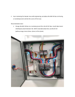
We installed (2) 400hz generators in a aviator manufacturing facility. Only (1) genset runs at a time and manual changed through a control cabinet. At start up the breaker trips, however after 2/3 attempts it holds and runs fine with no issues. We are feeding the genset with a 200A breaker and the settings have been dialed to the highest setting. We have checked inrush and it seems within the perimeters at 864 amps. I had the generator manufacturer out to take a look and in the link below is their suggestion. I have suggestion a VFD to the engineer but he seems to disagree beings that the inrush is within the perimeters.
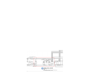
I have put in the link below the one line diagram, the genset tech's response. Below the link is the engineers response to the tech's.
https://drive.google.com/drive/folders/1n8_IcyCCqHj2nCdOHPySvb9438od9Dzf?usp=sharing
Some thoughts on manufacturer’s recommendations:
Per the NEC the 400 Hz system has to be grounded. This is accomplished by grounding the 400 Hz system neutral. This should have been done inside each 400 Hz generator with a bond jumper from the 400 Hz output neutral to the M-G set frame. Our drawings required that a #1/0 aluminum grounding electrode conductor run from the 400 Hz output neutral and frame to building steel. This is required by the NEC. Also, there is an equipment ground from the 60 Hz building system that runs to the 60 Hz motor frame (required by the NEC) that grounds the motor frame to the 60 Hz ground system.
• It is not clear to me how to isolate the 400 Hz system from the building’s 60 Hz system which is also bonded to the building steel.
• Is the M-G set frame constructed in a manner where the 60 Hz motor frame is already isolated from the 400 Hz generator frame or can it be isolated?
• If isolation of the 60 Hz and 400 Hz systems is achieved, what ground system should the sheet metal shielding be connected to?
• How can the sheet metal be installed to provide effective shielding? Maybe flexible metal conduit on all of the feeders the entire path to the contactors. I believe effective shielding will be difficult to achieve without rebuilding the entire control cabinet.
Thanks for any and all feedback!
We installed (2) 400hz generators in a aviator manufacturing facility. Only (1) genset runs at a time and manual changed through a control cabinet. At start up the breaker trips, however after 2/3 attempts it holds and runs fine with no issues. We are feeding the genset with a 200A breaker and the settings have been dialed to the highest setting. We have checked inrush and it seems within the perimeters at 864 amps. I had the generator manufacturer out to take a look and in the link below is their suggestion. I have suggestion a VFD to the engineer but he seems to disagree beings that the inrush is within the perimeters.
I have put in the link below the one line diagram, the genset tech's response. Below the link is the engineers response to the tech's.
https://drive.google.com/drive/folders/1n8_IcyCCqHj2nCdOHPySvb9438od9Dzf?usp=sharing
Some thoughts on manufacturer’s recommendations:
Per the NEC the 400 Hz system has to be grounded. This is accomplished by grounding the 400 Hz system neutral. This should have been done inside each 400 Hz generator with a bond jumper from the 400 Hz output neutral to the M-G set frame. Our drawings required that a #1/0 aluminum grounding electrode conductor run from the 400 Hz output neutral and frame to building steel. This is required by the NEC. Also, there is an equipment ground from the 60 Hz building system that runs to the 60 Hz motor frame (required by the NEC) that grounds the motor frame to the 60 Hz ground system.
• It is not clear to me how to isolate the 400 Hz system from the building’s 60 Hz system which is also bonded to the building steel.
• Is the M-G set frame constructed in a manner where the 60 Hz motor frame is already isolated from the 400 Hz generator frame or can it be isolated?
• If isolation of the 60 Hz and 400 Hz systems is achieved, what ground system should the sheet metal shielding be connected to?
• How can the sheet metal be installed to provide effective shielding? Maybe flexible metal conduit on all of the feeders the entire path to the contactors. I believe effective shielding will be difficult to achieve without rebuilding the entire control cabinet.
Thanks for any and all feedback!