I'm assisting a local non-profit with their irrigation system, and have found a mystery (to me). I'm a Electrical Engineer, not an Electrician.
The 3-phase 480v pump control panel isn't working, and the problem is that a low voltage relay is burned out (open coil). Why this relay is there at all is the mystery.
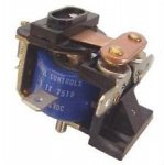
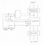
As with most such panels, there's a mechanical breaker with mechanical interlock, then a contactor, followed by an overcurrent device. Two inputs (of the three) terminals on the contactor go into a 480v:18v transformer. This low voltage is used to drive the contactor coil, once the correct switches are thrown and buttons are pushed. The mystery relay coil is also driven by the transformer output, and when closed allows all the low voltage wiring to work. It's a simple SPST relay, and if I just manually close the relay, everything fires up as expected. It's suffered a lot of heat damage, so an exact replacement is tricky, since the numbers are mostly gone. If the mechanical breaker is on, the relay is on - no other conditions can stop the relay from energizing. There's no sign of the wiring having been modified, since everything is nicely harnessed.
I can think of no reason the relay would be there except maybe it would prevent a brown-out on two of the phases (the ones driving the transformer and coil) from energizing the pump. If that's true, then the specs on the replacement coil are probably more critical than "18v SPST relay".
Am I missing something? Any reason to retain the silly thing?
The 3-phase 480v pump control panel isn't working, and the problem is that a low voltage relay is burned out (open coil). Why this relay is there at all is the mystery.
As with most such panels, there's a mechanical breaker with mechanical interlock, then a contactor, followed by an overcurrent device. Two inputs (of the three) terminals on the contactor go into a 480v:18v transformer. This low voltage is used to drive the contactor coil, once the correct switches are thrown and buttons are pushed. The mystery relay coil is also driven by the transformer output, and when closed allows all the low voltage wiring to work. It's a simple SPST relay, and if I just manually close the relay, everything fires up as expected. It's suffered a lot of heat damage, so an exact replacement is tricky, since the numbers are mostly gone. If the mechanical breaker is on, the relay is on - no other conditions can stop the relay from energizing. There's no sign of the wiring having been modified, since everything is nicely harnessed.
I can think of no reason the relay would be there except maybe it would prevent a brown-out on two of the phases (the ones driving the transformer and coil) from energizing the pump. If that's true, then the specs on the replacement coil are probably more critical than "18v SPST relay".
Am I missing something? Any reason to retain the silly thing?