pparana
Member
- Location
- Jacksonville Fl USA
Good evening,
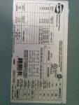
I am setting up a step down transformer for marine use, based on the attached diagram I am planning on feeding in to H1, H4 using the interconnect as spec'd. On the secondary I am planning on using 120/240 using the interconnect as spec'd. I believe x1 will be 120, x2 will be 0 and x3 will be 120. I am planning on bonding x2 to the grounding. This being on a marine application am I missing anything? This is feeding off of a primary generator located on the ship.
Thanks again Guys, can always count on this forum for solid information.