4W Neutral Current

Status
Not open for further replies.

That Man

Member
I can't quite tell if I'm having a senior moment, or if I've stumbled on something I haven't considered before, though I suspect it's the first one. I'm calculating voltage drops on a 3 phase 4 wire system where all the loads are single phase LN.

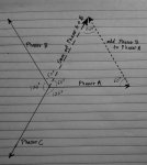
At the the end of the circuit there is a 3A load on phase A to N, so A current is 3A, N current is 3A.
Second to last load is 3A phase B to N, so B current is 3A, N Current is...
My guess is a phase shift of 60 degrees with an amplitude of 1.73x 3 = 5.2A.
First load is 3A phase A to N, so A current is 3A, N current is...
My guess is zero, as this N would cancel out the 2 other N's, so current at the N terminal from the source panel is zero.

Does this sound correct?
 

That Man

Member
A photo that tells the story better

A photo that tells the story better

Here's a photo that maybe explains it better.


3 phase 4 Wire Circuit.jpg
 

That Man

Member
So, I found a circuit simulator online. Turns out I wasn't quite there. Here's a screenshot:

3 phase 4 Wire Circuit Simulation.jpg

This tells me that only phase shifts occur, and there are no additive effects. So my diagram would look more like this:

3 phase 4 Wire Circuit New.jpg

So, from the source, 0A to the first load, 3A to the second load, 3A to the third load.
The phase angle is 0 degrees between the first and second load,
60 degrees between the second and third load,
and from the N to the second load is 30 degrees.

Interesting. I think I'm done, but I'll be monitoring this thread if anyone has any other comments.
 
Last edited:

LarryFine

Master Electrician Electric Contractor Richmond VA
Location
Henrico County, VA
Occupation
Electrical Contractor
So, from the source, 0A to the first load, 3A to the second load, 3A to the third load.
This is correct. Start with all three 3a loads, zero neutral current.

Now, reduce one load by 1a. What happens to the neutral current?

It rises by that same one amp. Now do the same with 2a or with 3a.
 

synchro

Senior Member
Location
Chicago, IL
Occupation
EE
190730-0903 EDT

That Man:

You need to take the phasor (vector) sum of the currents.

.

Which in this case is easy to do:

View attachment 23446

You can see that the vector summation of phasors A and B has the same magnitude as them (and therefore an equal RMS current), and also the phasor sum is +- 60 degrees from phasors A and B respectively. This is because they form an equilteral triangle with equal sides and all 60 degree angles.

You can also see that the phasor sum is 180 degrees from phasor C and so they all cancel when C is added in.

If you were interested in the vector difference between A and B (for example if they were wye phase voltages and you wanted the line voltage) then the resulting magnitude would be sqrt (3) times that of one phase.
 

That Man

Member
Thanks for the follow-ups everyone. I was trying to develop a simplification of 3 phase 4 wire unbalanced voltage drop that avoids the vector arithmatic, and I think I've got it. I don't think I can take it any further without introducing vectors, and at that point, I would use the phasor diagram method, as it will handle differing power factors. Phasors don't fit neatly on a drawing though, when you have a couple dozen legs to calculate. Here's what I've come up with:

In -drawing Vd Calc.jpg
 
Status
Not open for further replies.
Top