The first thing after the fuses is a line reactor, aka "AC choke", then below that is an 18 pulse transformer, used to help try to mitigate the harmonics. It's going to have 3 phases in, 9 phases out in three sets of three phases, each one phase shifted by (usually) 20 degrees. That then feeds 18 diodes all configured as 3 separate bridge rectifiers, then those all feed a common DC bus for the VFD. The 18 pulse diode bridge is over to the right side under the two fuses. Here's a general schematic, although it doesn't have the line reactor ahead of it (or the DC link fuses).

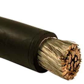
One thing I would suspect in your panel is that those cables from the breaker to the fuse block appear to be extra flexible cables, meaning a high strand count, probably Class K stranding or higher. That kind of cable requires special compression lugs and dies for the tools. The bottom lugs (attaching to the fuse block) and those on the reactor and transformer appear to be factory machine made, but are different from those attaching to the breaker. So I would suspect that at the breaker end the compression, lug, die or all three were incorrect or incorrectly done, leading to an overheated connection and eventual melting of the conductor. I've seen that too many times; people don't understand that the high flex cable needs special connections.
I don't know if that was a Sq. D factory built 18 pulse drive or not, even though all the parts are Sq. D. Part of my reason for doubting it is that someone put fuses on the DC link, which is not something a VFD mfr. typically does, it's something that is done by someone who is being overly cautious.