Julius Right
Senior Member
- Location
- Israel
- Occupation
- Electrical Engineer Power Station Physical Design Retired
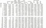
Attached is a list for AWG or kcmil[MCM] at 30oC.I did for 75oC also and is 1-3% different from NEC Table 9 [pvc conduit].May be because at NEC the result is rounded.
I am sorry. The list of #21-RAC 30oC AWG_mcm is wrong. For the
kcmil 250-2000 I put the 25oC dc resistance in ohm/km instead of
ohm/kft. I APOLOGIZE for my mistake and here attached the corrected list.
")
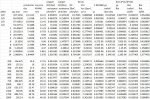
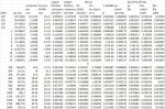
I think I found why NEC is 1-3% different. NEC team followed Neher and McGrath way calculation. This way is based on tables and curves rather than formulae. It seems to me this system is a little more accurate-a bit-but it is not so practical. Here attached it is the 150 oC copper conductor a.c. resistance table.
Up to 6 awg it is no difference between dc and ac indeed. However ,up to 3/0 the difference it is less than 1%.Up to 600 mcm the difference increases up to 10% and for 2000 mcm it is more than 50%.
Up to 6 awg it is no difference between dc and ac indeed. However ,up to 3/0 the difference it is less than 1%.Up to 600 mcm the difference increases up to 10% and for 2000 mcm it is more than 50%.


If you intend to follow N-McG method it is difficult to calculate since here for ys [skin effect] and yp [proximity effect] functions F(x) and F(p) are in tables using about 500 numbers. I think the base of this table calculation is using Bessel function but I not yet found how.
I follow IEC 60287-1-1 method-there using formulas which may introduce an error of 1 to 4%. That, in my opinion, is enough accurate.
I have no problem to do an excel sheet where you may chose conductor temperature and ambient and other for ac resistance calculation. The problem is I cannot attach an excel spreadsheet in this forum-only jpg file may be attached here.
Thank you for the reply.If you intend to follow N-McG method it is difficult to calculate since here for ys [skin effect] and yp [proximity effect] functions F(x) and F(p) are in tables using about 500 numbers. I think the base of this table calculation is using Bessel function but I not yet found how.
I follow IEC 60287-1-1 method-there using formulas which may introduce an error of 1 to 4%. That, in my opinion, is enough accurate.
I have no problem to do an excel sheet where you may chose conductor temperature and ambient and other for ac resistance calculation. The problem is I cannot attach an excel spreadsheet in this forum-only jpg file may be attached here.
I'm not sure, but since NEC is the law, I have to say it's the right value.
I'm not sure, but since NEC is the law, I have to say it's the right value.
Can you explain when to use coated or uncoated ?