Adding a bypass to an existing VFD

Status
Not open for further replies.

SSDriver

Senior Member
Location
California
Occupation
Electrician
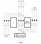
I need to add a bypass to a pump that is currently running on a VFD in case the VFD needs repair. I was planning on using 3 contactors and had a few questions. It will also have an HOA switch (VFD - OFF - Bypass) run from a control transformer not in my diagram that would power the 3 contactors in this bypass cabinet. The RIGHT and LEFT contactor would get power with the switch in VFD mode and the Center contactor would get power with the switch in Bypass mode.

Questions
1.
I'm assuming I would want to remove the OL Relay in the VFD?

2. If I remove the OL in the VFD I would run the NC contacts from the removed VFD OL relay and run it to a set of NC contacts mounted to the center contactor in my diagram. The NC contacts on my diagrams OL Relay would go to the center contactors coil. Is this correct?

3.
I was planning on having a Mechanical interlock between the CENTER and Right contactor. I wasn't sure if I should or would need another mechanical interlock on the LEFT and CENTER. I was worried that having multiple mechanical interlocks could cause issues with them jamming up when the LEFT and Right contactors are closing at the same time.

4. Do I need to add an stop signal somewhere to stop the VFD run command in case someone shuts the pump down via the bypass cabinet instead of the drive by accident?

5. What am I missing?
 

Attachments

  • vfd bypass.jpg
    vfd bypass.jpg
    146.5 KB · Views: 44
A. I do not see a need to directly remove the input power from the VFD as part of the transfer. You will want a manual disconnect to allow the VFD to be repaired.
B. During normal operation, the OL function will be performed by the control logic of the VFD, not by a discrete overload relay.
C. To prevent damage to the VFD the enable command to the VFD should be removed before or at the same time as the disconnect of the motor load. Just removing VFD input power is not sufficient for protection since the DC bus capacitors will keep the VFD active long enough for damage to occur.
 
A. I do not see a need to directly remove the input power from the VFD as part of the transfer. You will want a manual disconnect to allow the VFD to be repaired.
B. During normal operation, the OL function will be performed by the control logic of the VFD, not by a discrete overload relay that can be removed.
C. To prevent damage to the VFD the enable command to the VFD should be removed before or at the same time as the disconnect of the motor load. Just removing VFD input power is not sufficient for protection since the DC bus capacitors will keep the VFD active long enough for damage to occur.
 
Last edited:
I would suggest that you only consider a manufacturer's bypass assembly that is NRTL listed with the existing VFD, so the short circuit rating for the overall package is adequate and listed together for safety. In bypass, you need to isolate the VFD for service in an open transition methodology and not backfeed the VFD.

I would also suggest that this is not a simple as just adding the bypass. When I do a short circuit, coordination and arc flash study, I discount the motor contribution back into the system when there is a VFD with no bypass, since the solid state circuitry of the VFD will not allow backfeed of the motor contribution into the system. You need to be sure that by adding the bypass you are not causing that study (if one has been done) to have to be redone. I usually just suggest, rather than going through this exercise of adding bypass, that the ops staff just buy a spare matching VFD to have in stock in case the VFD goes "south" for a critical load since they are relatively cheap nowadays. Also, what if the source can't handle the inrush of an across the line start......
 
I would also suggest that this is not a simple as just adding the bypass.

Don't forget the pumping system being controlled by the VFD. Is the process even capable of running at 100% speed. I know many MEP engineers like to specify VFD-bypass for their mechanical systems, but most building operators I have met dread the idea of going to full speed or manually throttling. Industrial systems rarely have full speed bypass installed.

Consider adding a spare VFD into inventory or one wired in like your bypass contactor.
 
Franklin makes stand alone 3 contactor bypass systems as a standard part. You mount it above or next to the VFD, ANY VFD. The run signal goes into the bypass and there are 4 sets of power connections (power, motor, VFD power, VFD output). Cheaper to do it this way than build your own. Following this as a design works well.

The way all bypasses work is there is both an input and output contactor on the VFD and a separate conventional starter. Plus mechanical relays to handle the switching or a small smart relay or PLC with a small screen or some pilot lights. It’s easiest to use a small PLC if you build your own. The “starter” can be a combination starter, a soft start, or a second VFD.

The VFD line side contactor CAN be just a disconnect but then you get this strange situation with two lockout points for the conventional bypass but makes sense in this use case. This is where history on bypasses matters. Back in the 1970s and 1980s VFDs used forced commutation. They literally had to short out an SCR with another SCR to get it to open. Blowing up SCRs then GTOs was a routine thing. So bypass contactors were a necessity, not a paranoid option. In the 1990s VFD reliability went up dramatically. Today realistically bypassed VFDs have a lower reliability than bypassed systems. So the contactors were just that. The disconnect point for LOTO is on the whole system unlike say UPS bypasses. What you want is more similar to a UPS so using a separate disconnect on the PKC, even a manual motor starter (cheap) is the way to go and different from what the standard bypassed VFD is.

The NRTL comment is ridiculous. It’s an industrial control panel. Build to those Codes which usually means 809A but some plants don’t require that. VFD manufacturers have nasty warnings about contactors because if you cycle the input power too quickly on the VFD you will burn up the precharge circuit.

Forget any overload games. You can’t really use an overload directly on VFD output. The POWER is accurate but current alone is not the way to do overload protection on a VFD which is why this function should be in the VFD. Plus for the standard use case (VFD fails) you don’t want to rely on it if you could. The starter needs its own.

Realistically though as a backup bypass systems are pretty limited. At the end it’s almost easier to just put in a second system and be done with it. Pump mechanical failures are far more common but people go crazy on doing complicated bypass systems. A duplex pump station is very reliable and used extensively in sewage collection systems for a reason,
 
Thanks for the input. I looked at the Franklin bypass assemblies and they look like they operate almost the same as my diagram. The interlocked contactors would keep the VFD from being backfed. The Franklin bypass has the same setup as I proposed with a contactor to prevent power going to the VFD on the LINE side and two contactors interlocked with an OL on the LOAD side. I'm assuming they have the enable command being interrupted when in bypass as well. After looking at their diagram the only difference is they have the VFD output going to the motor AFTER the OL relay and not before as in my diagram. So I could switch that.
 
Thanks for the input. I looked at the Franklin bypass assemblies and they look like they operate almost the same as my diagram. The interlocked contactors would keep the VFD from being backfed. The Franklin bypass has the same setup as I proposed with a contactor to prevent power going to the VFD on the LINE side and two contactors interlocked with an OL on the LOAD side. I'm assuming they have the enable command being interrupted when in bypass as well. After looking at their diagram the only difference is they have the VFD output going to the motor AFTER the OL relay and not before as in my diagram. So I could switch that.

1. The run command goes through the bypass. Remember it has a “auto/off/hand” and bypass functions. If you only feed enable/interlock and send run to the VFD you can’t start the bypass contactor and the other two contactors aren’t synchronized to the VFD either. Externally except “speed” the external (PLC/SCADA) system connects to the bypass controller which in turn controls the VFD. That way you can freely swap VFDs and the bypass is transparent.

2. It is a common mistake to think that current is the same in a VFD system so overloads work the same. It does NOT. Power is the same but since voltage must be adjusted, current is no longer a simple way of measuring load. Many electricians are shocked to see nearly FLA on a drive running at low speeds. This is normal. Ignoring vector control v/hz is almost constant. So Amps at low speeds is high but power is low. Hence using an overload relay on a VFD is not the right way to do it.
 
...

2. It is a common mistake to think that current is the same in a VFD system so overloads work the same. It does NOT. Power is the same but since voltage must be adjusted, current is no longer a simple way of measuring load. Many electricians are shocked to see nearly FLA on a drive running at low speeds. This is normal. Ignoring vector control v/hz is almost constant. So Amps at low speeds is high but power is low. Hence using an overload relay on a VFD is not the right way to do it.
OL relays react to amps, not power. Amps are amps are amps. In fact up until about 2002 when UL changed the testing and listing rules for VFDs to require that they provide motor OL protection, a lot of low-end VFDs did not come with OL protection, you had to add it as a separate OL relay (leading to a LOT of motors burning up in the field because people didn't read the installation manuals...). All VFDs are now required to have OL protection so that is no longer nevessary, but there is no serious problem with having one.

Now, it is true that bi-metal OL relays have a tendency to nuisance trip because of the non-sinusoidal waveform, and many Solid State OL relays can't work on the output of a VFD because they use different types of current sensors. But that doesn't mean you can't use OLs on the output of a VFD. In fact you are REQUIRED to if there is more than one motor on the VFD output. Melting alloy OL relays are the best choice, unless a specific bi-metal or SSOL specifically is rated for use on the output side.

The advantage to having the OL relay in the circuit all of the time is because it will then "know" the actual motor thermal condition regardless of how it was being run. So for example let's say you have the OL only on the bypass starter and have been running the motor on the VFD. The VFD fails and the motor is switched to the Bypass starter. That motor is ALREADY hot, but the OL relay "thinks" it is cold, because up to that point the current through the OL relay was zero. What can (and has) happen is that the motor burns up because of the slower than normal response time of the OL relay.
 
A. I do not see a need to directly remove the input power from the VFD as part of the transfer. You will want a manual disconnect to allow the VFD to be repaired.
B. During normal operation, the OL function will be performed by the control logic of the VFD, not by a discrete overload relay.
C. To prevent damage to the VFD the enable command to the VFD should be removed before or at the same time as the disconnect of the motor load. Just removing VFD input power is not sufficient for protection since the DC bus capacitors will keep the VFD active long enough for damage to occur.
I agree on all counts.
But, the ability to disconnect the line side of the VFD might be important for being able to remove it for servicing if you cannot shut down the motor. If that's the case, make sure they are in separate enclosures for NFPA70E purposes.

See my previous response for why you might want to leave the OL relay in all of the time. But to add to that, IF the process of switching to Bypass is a manual one and a lot of time will go by before someone changes over, the motor may be cooled off anyway by then, in which case having the OL in the circuit all of the time becomes a moot point.

Also, to Bob Petersen's point, if this will end up being a manual process of changing to bypass anyway, you can just use a manual transfer switch and a manual motor starter to protect the motor. Cheap, simple, failsafe. There is a company that makes an Inverter Bypass Switch, called an IBYSS, but really, any manual transfer switch will do.
 
Status
Not open for further replies.
Top