Are these Feeder Sizes right?

LA-Sean

Member
Location
Los Angeles
Occupation
General Contractor
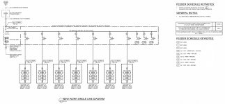
Doing a Main Panel Upgrade for an Apartment Building. It has 6 Apartment Units, 1 House Panel, and 3 Spare Meters. The Utility has approved us for One Drop of 400Amp. Its not much but we want to over size the Unit for future electrical deployment. As you can see from Each of the Single-Line Diagram the Sub-Panels will have a 200A Bus. The Feeder Schedule doesn't make sense to me. I believe all the Feeders from the Main to the Main Panel to the Sub-Panels should be set to (1) 2"C - 3#1 +1#8 GND. What are you thoughts? If you need additional information to form an opinion. please feel free to ask. Feeder Size Verification on Single-Line Diagram.jpg
 

infinity

Moderator
Staff member
Location
New Jersey
Occupation
Journeyman Electrician
I believe all the Feeders from the Main to the Main Panel to the Sub-Panels should be set to (1) 2"C - 3#1 +1#8 GND. What are you thoughts?
How did you come up with those wire sizes? It shows a 200 amp OCPD ahead of those panel feeders.
 

LA-Sean

Member
Location
Los Angeles
Occupation
General Contractor
Hi Infinity. Are you speaking about the Feeder Schedule Keynotes? Those were provided on the Drawing by the Electrical Engineer. I believe they are wrong. I have tried connecting him to discuss but he has since dropped-off the face of the Earth. That is why I am reaching out on this forum to see if I can get some help. From past experience I believe the feeder size 2"Conduit - 3 of the #1 Wire +1 of the #8 Wire for GND from the Main Panel to all the Sub-Panels. But I could be wrong.
 

infinity

Moderator
Staff member
Location
New Jersey
Occupation
Journeyman Electrician
From past experience I believe the feeder size 2"Conduit - 3 of the #1 Wire +1 of the #8 Wire for GND from the Main Panel to all the Sub-Panels. But I could be wrong.
From what's is shown on the drawing you are incorrect. Each meter has a 200 amp OCPD after it with a feeder to the sub-panel. That feeder needs to be rated for 200 amps so for Cu #3/0 is required.
 

Elect117

Senior Member
Location
California
Occupation
Engineer E.E. P.E.
For MLO, 200A is a minimum of 3/0 copper thhn/thwn with a #6 ground. I cant tell from the drawing which feeder applies to what on the single line. My guess is they are all E6.

Please refer to the table 310.16 for conductor ampacity.

Infinity beat me to it.
 

LA-Sean

Member
Location
Los Angeles
Occupation
General Contractor
E6 on the Feeder Schedule Keynotes says: "(1) 2"C - 3#3/0 + 1#6 GND. I don't see E6 on the Single-Line Diagram. Only on the Keynotes. So, I should be good with running that to all the Sub-Panels?
 

Elect117

Senior Member
Location
California
Occupation
Engineer E.E. P.E.
E6 on the Feeder Schedule Keynotes says: "(1) 2"C - 3#3/0 + 1#6 GND. I don't see E6 on the Single-Line Diagram. Only on the Keynotes. So, I should be good with running that to all the Sub-Panels?

The plans look incomplete. I would suggest asking a different engineer to review the plans or your electrical contractor. There is no voltage drop number near the ":" on the plans. The footages for each panel are also identical which is odd. Your electrical contractor should be able to verify this as well.

Normally 3/0 is the minimum wire size but there are times when you need a larger wire size by code. For example, voltage drop.
 

augie47

Moderator
Staff member
Location
Tennessee
Occupation
State Electrical Inspector (Retired)
Another oddity (IMO) is the wording mentions a MCB but the drawing doesn't show one and that many 200 amp panels from a 400 amp buss is unusual to say the least, A load calculation would be interesting.
 

infinity

Moderator
Staff member
Location
New Jersey
Occupation
Journeyman Electrician
Another oddity (IMO) is the wording mentions a MCB but the drawing doesn't show one and that many 200 amp panels from a 400 amp buss is unusual to say the least, A load calculation would be interesting.
Seems like a 3Ø service with 1Ø panel feeders would be more inline with 7-200 amp panels on a 400 amp service. And where is the service disconnect?
 

curt swartz

Electrical Contractor - San Jose, CA
Location
San Jose, CA
Occupation
Electrical Contractor
This drawing needs to get dropped into the paper shredder.

Using 3/0 for the feeders is common sense but the drawing should show that.

As Augie stated you should have a main breaker. You have 10 service disconnects.

The drawing also shows the utility ISC of 30K with 27K at the unit panels. The meter center and unit panels are spec'd as 22K.
 

jaggedben

Senior Member
Location
Northern California
Occupation
Solar and Energy Storage Installer
Since you said these are apartments, 310.12 probably applies and you can use 2/0 cu from each 200A breaker to each panel.

I agree the 400A service disconnect seems to be missing from drawing: the note refers to a 400A MCB but it's not shown.

The Feeder Schedule keynotes don't seem to me to actually refer to anything in the drawing. Seems like a copy/paste from something else.
 

CoolWill

Member
Location
Alabama
Occupation
Electrical Contractor
Apparently, the available fault current gets higher the further you are away from the transformer. You might have some sort of free energy device on your hands here
 
Top