grantcool
Member
- Location
- Atlantic Beach, Florida
i asked this question in code class and couldn't get an answer (dissapointing).
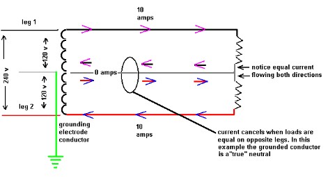
on a balanced 20 amp circuit, 2 equal 120 volt loads, the shared neutral carries no current. but if the loads are rated at 120 volts, and the current doesn't return on the neutral, does it return on the other phase? wouldn't that put 240 volts across each 120 volt load?
on a balanced 20 amp circuit, 2 equal 120 volt loads, the shared neutral carries no current. but if the loads are rated at 120 volts, and the current doesn't return on the neutral, does it return on the other phase? wouldn't that put 240 volts across each 120 volt load?
") )
)