zbang
Senior Member
- Location
- Roughly 5346 miles from Earls Court
it was labeled "blocking diodes"
To me, the term blocking diode is wrong, but it sounds like an excellent place to use steering diode- it steers the current to the right place.
it was labeled "blocking diodes"
The lockout relay would have other contacts in the closing circuit of the breakers (not shown), this device is usually manually operated. After a fault someone has to manually reset it before the breaker can be closed back.
For the circuit at hand, automatic operation to transfer from a failed line to a good line can occur as many times as required. If an overcurrent device operates the automatic operation is halted by the lockout relay to prevent the second good line from closing in on the same fault. Before a lockout relay is reset, one needs to be sure the fault was located and repaired.
No intentional time delay is intended with the lockout relay, its just a limitation of the mechanical device. The overcurrent devices shown on the schematic were all time delay (51). The extra time to clear the fault probably did not matter, those devices are adjustable & could be set to compensate the extra time. They are pretty interesting in that they mimic fuse curves & can be coordinated with fuse protection.
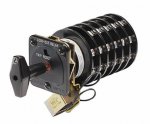
The one line did show an instantaneous overcurrent device (50). The diode may have been added after the fact, so as to not delay the instantaneous trip. Below is a picture of a modern lockout relay. The length varies with the number of breakers controlled. The 52 is a three phase circuit breaker ,it probably approaches one ton in weight.
The diode was added after the fact...many years after original installation.
So it is not common then to have a single LOR be use as a junction point to trip two incoming feeders? Again, in this case, we have two MV feeders coming to and lugged together to supply the primary side of the substation (switchgear) transformer. It looks to be that if there is an overload, the weather at the substation or a fault on the feeder, the only way to trip the other MV feeder had been through the 86 LOR contact. So, to ensure on overload that both feeders are isolating, my understanding is that the diode was added to ensure current would get sent to both trip coils. The directional bias of the diode would prevent current flow if say the UV relay trip and thus allowing the other feeder to continue operating.
I think we are all in agreement then and these steering diodes should be kept because it looks like there was a benefit to someone installing them?
Benefits:
1) Decreased time required to trip both circuit breakers
2) Redundancy in trip signal if the 86 LOR fails to close, the diode would ensure current flow to the other trip coil regardless of whether or not the 86 contacts actually closed.
Thanks!
I am clearly in agreement with keeping the diodes.
I would say that for two incomers serving the same load a lockout relay would be standard equipment.
One does not want the second line to close into the same fault that opened the first line. The lockout is still the standard way to prevent this undesired operation from occurring.