What if we combine these two systems assuming there is an earthed neutral point and a separate grounding conductor goes to the building and is combined with the building grounding electrode systems so that there is a much more effective and low impedance grounding system (Except cost concerns, is there any impediment to such a scheme in terms of safety? )
You are using an out of date browser. It may not display this or other websites correctly.
You should upgrade or use an alternative browser.
You should upgrade or use an alternative browser.
Bonding TT and TN-S
- Thread starter electrics
- Start date
- Status
- Not open for further replies.
- Location
- Illinois
- Occupation
- retired electrician
The use of the terms "TT" and "TN-S" is not common in the US and many forum members will have no idea what you are asking about. You may want to define those terms.What if we combine these two systems assuming there is an earthed neutral point and a separate grounding conductor goes to the building and is combined with the building grounding electrode systems so that there is a much more effective and low impedance grounding system (Except cost concerns, is there any impediment to such a scheme in terms of safety? )
The use of the terms "TT" and "TN-S" is not common in the US and many forum members will have no idea what you are asking about. You may want to define those terms.
what if PE is connected to the building grounding electrodes?
Is it better to use this scheme? Or the schemes separately better? (this very same system without PE is better or the same system without building grounding electrodes this time instead of PE better in terms of safety
 ?
?Attachments
mbrooke
Batteries Included
- Location
- United States
- Occupation
- Technician
What if we combine these two systems assuming there is an earthed neutral point and a separate grounding conductor goes to the building and is combined with the building grounding electrode systems so that there is a much more effective and low impedance grounding system (Except cost concerns, is there any impediment to such a scheme in terms of safety? )
If you ran a separate PE from the transformer XO to the ground bar of a TT system you would then have a TN-S system which are considered the most safe and advanced of all systems today. A down side might be higher fault current yes, but if an RCD failed to trip in a TT system you would have an energized grounding system, both a shock/electrocution hazard and a fire hazard. It this reason why some electricans like to put 2 RCDs in series on a TT earth. Running a PE from the XO to the buildings grounding system will clear a fault no matter what, even if an RCD failed.
TN-S or TT, its always a good idea to have your foundation bonded and to have ground electrodes.
")
The use of the terms "TT" and "TN-S" is not common in the US and many forum members will have no idea what you are asking about. You may want to define those terms.
Yes these terms are not common to the NEC or CEC but IMO these are terms that many forum member should know since its the correct way to describe power systems through out most of the world.
Last edited:
If you ran a separate PE from the transformer XO to the ground bar of a TT system you would then have a TN-S system which are considered the most safe and advanced of all systems today. A down side might be higher fault current yes, but if an RCD failed to trip in a TT system you would have an energized grounding system, both a shock/electrocution hazard and a fire hazard. It this reason why some electricans like to put 2 RCDs in series on a TT earth. Running a PE from the XO to the buildings grounding system will clear a fault no matter what, even if an RCD failed.
TN-S or TT, its always a good idea to have your foundation bonded and to have ground electrodes.
Yes these terms are not common to the NEC or CEC but IMO these are terms that many forum member should know since its the correct way to describe power systems through out most of the world.
why is it the case that this way a common scheme like this will clear the fault even if rcd does not trip. Just because impedance gets lower?
mbrooke
Batteries Included
- Location
- United States
- Occupation
- Technician
why is it the case that this way a common scheme like this will clear the fault even if rcd does not trip. Just because impedance gets lower?
A properly sized copper or aluminum conductor (say as big or at least 1/2 the size of the actives) will have a much lower impedance that ground rods.
Think ohms law. A PE back to the XO bushing will be at most 0.05ohms, a ground rod may be 50ohms. Higher or lower depending on depth, soil material and moisture content. At 230 volts phase to ground a PE at 0.05ohms will let through 4,600amps during a fault (assuming infinite available fault current from the transformer which works for most scenarios) Now, if we were to rely only on the ground rods, at 50ohms they would only pass 4.6 amps, at 25ohms they would pass 9.2 amps. Not enough to trip the breaker. Even a really low resistance such as 10ohms would only pass 23 amps. These values would never trip a breaker. The last one might trip a smaller 10 amp breaker but only after some time. It is for this reason TT needs RCDs to clear a fault. TN earthing doesnt since it has a low impedance path back to the source.
The earth in general is a poor conductor. TT is cheaper on long runs since you only need 4 wires on a 3 phase system, or 2 going to a home. However more cost at the electrical box in the building since RCDs will be mandatory. TN-S requires 5 wires, 3 to a home, but its the safest. In terms of clearing direct faults RCDs are not needed. Some times they are required for added saftey, but are not essential to detecting an active touching a ground wire.
mbrooke
Batteries Included
- Location
- United States
- Occupation
- Technician
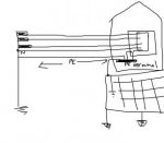
I am asking it since to have a system like in the given illustration seem to me very safe , but I am not sure if there is a drawback with this scheme, because I could not find a combined scheme such as this one..
Adding more electrode to the transformer ground and the buildings ground lowers earth resistance but rarely to a value to trip a breaker. It gets to a point where if you were trying to get an earth resistance of only an ohm so many electrodes would be involved and driven at such a depth it would become more expensive then running a PE.
- Location
- Illinois
- Occupation
- retired electrician
While they are used in the rest of the world, there is no need to know or understand them to correctly apply the NEC or to design and install a safe electrical system in the US....
Yes these terms are not common to the NEC or CEC but IMO these are terms that many forum member should know since its the correct way to describe power systems through out most of the world.
Also why are they correct way to describe power systems? Why are not our terms the correct way?
mbrooke
Batteries Included
- Location
- United States
- Occupation
- Technician
While they are used in the rest of the world, there is no need to know or understand them to correctly apply the NEC or to design and install a safe electrical system in the US.
Also why are they correct way to describe power systems? Why are not our terms the correct way?
Those terms aren't all inclusive or the only way to describe power systems, yes, but they cover a broader range of variants. For example there is no way to describe a TT system since its forbidden by the NEC. TN-S is not something supplied by utilities but mandatory for separately derived systems. An easier way of saying separate ground and neutral all the way to the XO bushing. TN-C-S being short for neutral and ground function combined till a designated point. IT (or unearthed neutral) better describes ungrounded power since the term ungrounded has many meaning entirely based on how its used. IMO it just makes it easier to describe a long list of system variants.
Last edited:
Tony S
Senior Member
- Location
- Resting under the Major Oak UK


There is also PME which is TT with multiple neutral earth connections. Sorry I can?t find the picture for this.
If the OP is UK based he should have this information in BS7671R2 or the OSG to hand.
PE can be connected to the consumers earth and frequently is via extraneous conductive parts of a building.
Only the DNO (supply company) can make a neutral earth connection at the customers service cut-out. After the cut-out they must be separate.
Tony S
Senior Member
- Location
- Resting under the Major Oak UK
Those terms aren't all inclusive or the only way to describe power systems, yes, but they cover a broader range of variants. For example there is no way to describe a TT system since its forbidden by the NEC. TN-S is not something supplied by utilities but mandatory for separately derived systems. An easier way of saying separate ground and neutral all the way to the XO bushing. TN-C-S being short for neutral and ground function combined till a designated point. IT (or unearthed neutral) better describes ungrounded power since the term ungrounded has many meaning entirely based on how its used. IMO it just makes it easier to describe a long list of system variants.
IT is earthed (grounded) via a NER. IT Impedance Terre. Used mainly for MV distribution 11, 6.6 & 3.3KV.
An un-earthed neutral can't be used for LV distribution.
mbrooke
Batteries Included
- Location
- United States
- Occupation
- Technician
IT is earthed (grounded) via a NER. IT Impedance Terre. Used mainly for MV distribution 11, 6.6 & 3.3KV.
An un-earthed neutral can't be used for LV distribution.
:blink:
Im not sure what BS7671 allows for a public supply, but there are countries that apply an "unearthed neutral" IT 230 volt supply. Usually these systems are only 3 wire with or without ground interconnecting structures and fed via a 230Y/133 volt transformer. The XO is either left floating or more generally grounded via "impact protection". Its just a fancy surge arrestor that shorts the XO to ground if the MV crossed into the LV. This was the norm in Norway to supply domestic customers. IT earthing is extensively used in hospitals, industries and the like all over the world where power interruptions cant be tolerated. Ive heard of a few developing countries using 400Y/230 and leaving the neutral floating, but this system in particular is not recommended nor a god idea.
If you don't believe me this explains the concept:
http://www2.schneider-electric.com/documents/designers/top-downloads/090197c6800bcbde_.pdf
If the OP is interested: http://www2.schneider-electric.com/...ility-safety/low-voltage-minus-1kv/ect173.pdf
Last edited:
mbrooke:
A ground resistance, even if of high value, may be desirable to be connected across neutral to ground of an IT system because it stabilises phase to ground voltage. If there is no neutral to ground resistance, the phase to ground voltage in an IT system may be of any value, perhaps even high enough to cause insulation breakdown.
A ground resistance, even if of high value, may be desirable to be connected across neutral to ground of an IT system because it stabilises phase to ground voltage. If there is no neutral to ground resistance, the phase to ground voltage in an IT system may be of any value, perhaps even high enough to cause insulation breakdown.
Also why are they correct way to describe power systems? Why are not our terms the correct way?
Theirs (the European) is comprehensive way and yours (the American) is practical way to describe power systems.
Which one is preferable?
Obviously it depends where one is: When in Rome, be a Roman.
Last edited:
mbrooke
Batteries Included
- Location
- United States
- Occupation
- Technician
mbrooke:
A ground resistance, even if of high value, may be desirable to be connected across neutral to ground of an IT system because it stabilises phase to ground voltage. If there is no neutral to ground resistance, the phase to ground voltage in an IT system may be of any value, perhaps even high enough to cause insulation breakdown.
I agree. If one was to select a resistance value that by itself produces current draw slightly over the normal phase to ground capacitance than most of the risk of damamge from arcing ground faults its eliminated. Another method is a properly rated reactor that is in "tune" with the phase to ground capacitance. "Peterson coil earthing" is one name for this.In IT systems such as those serving 120 and 230 volt recptacles in hospitals the norm is a pure ungrounded system where no deliberate impedance of any kind is inserted on either of the legs or the XO. On large industrial systems today the norm is either a resistor or reactor of sufficient size to eliminate destructive surges from an arcing fault.
The reason is a s?ngle phase system from high resistance grounded three phase system should not be used. I think there is a code prohibition for that.In IT systems such as those serving 120 and 230 volt recptacles in hospitals the norm is a pure ungrounded system where no deliberate impedance of any kind is inserted on either of the legs or the XO. On large industrial systems today the norm is either a resistor or reactor of sufficient size to eliminate destructive surges from an arcing fault.
Tony S
Senior Member
- Location
- Resting under the Major Oak UK
There are many forms of IT.
As has been mentioned medical applications (BS7671 has a whole new section to cover that).
In my case I?ve been involved with them on 11 and 3.3KV distribution where NER?s are used to limit earth fault currents.
Induction furnaces, the conductors and coils are water cooled so to provide a solid earth would be disastrous.
Mines and quarries, again to limit earth fault currents. (BS7671 doesn?t have a section for that).
But they aren?t used for general distribution. Which I believe is what the OP was asking about.
Last edited:
- Location
- Illinois
- Occupation
- retired electrician
Exactly...the one that is preferable to me is the one that I use...don't really care what the rest of the world does as it doesn't make any difference to meTheirs (the European) is comprehensive way and yours (the American) is practical way to describe power systems.
Which one is preferable?
Obviously it depends where one is: When in Rome, be a Roman.
- Status
- Not open for further replies.