big john
Senior Member
- Location
- Portland, ME
We have a bunch of ungrounded 600V systems. The only ground detection we have on them is some high-voltage wye-connected neon lamps.
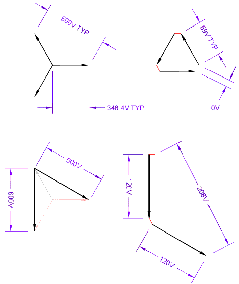
I'm looking to install a broken-delta transformer so I can operate a ground detection relay. I'll be making it out of three 600:120 transformers; solidly grounded wye-connected primary; ungrounded open-delta secondary with a burden resistor.
My questions:
I'd like to keep some sort of indicator lamp scheme to see what phase has the fault, but I don't want them connected to the 600V primary. I've seen a diagram where each ground-fault lamp was connected in parallel with one of the secondary windings of the broken delta. Would that work? Would they still operate in the same fashion that they do now? (And if so, how?)
Also, I'm 99% sure that during a ground fault, the maximum voltage across the break in my delta will be 120V. I'm having trouble understanding why, though, and vector math doesn't mean much to me. Any help there?
Thanks a bunch.
-John


