Buck Boost Transformers / 3 Phase using 2 Single Phase Buck Boost Transformers

FlyWhale

Member
Location
NC
Occupation
Electrician
Hey guys, I have looked all over the forum and beyond for help on buck boost wiring. I believe I have an understanding of Single Phase Buck Boost Transformers but when I try to apply the math to a 3 Phase System. I am not coming out with numbers that make sense. I hope that the forum community can shed some light.

I do have a specific question in mind but I'd like to ask a general question to help me, and hopefully others, grasp the method of bucking or boosting a 3 phase system to a different 3 phase voltage using 2 Single Phase Buck Boost Transformers. This may be the key for my other question and probably the rest to come.

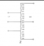
The photo attached is one of the wirings in question.

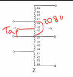
According to this diagram, I will get 208V between A+B and B+C but not A+C. Does that sound correct?

For example, I have 218V Input and I want a 208V Output. This wiring configuration only drops voltage on A and C Leg.

I cannot run a 208V 3 Phase Equipment with significantly lower voltage between the A+C Leg . Yet, this is the diagram I was referenced to from the Buck Boost Transformer.
I believe my math or my understanding..or both... is incorrect somewhere.

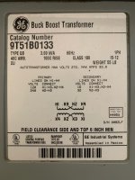
I've attached a photo of the nameplate of the transformer to assist with any info.

I'd appreciate any help.
 

Attachments

  • 1708197535997.png
    1708197535997.png
    37.6 KB · Views: 17
  • IMG_1629.jpg
    IMG_1629.jpg
    817 KB · Views: 15
What you're missing is to look at the delta as an equilateral triangle with one side missing; what we call an open delta. As you shorten the two remaining sides, the tips of those two lines also get closer.

Thus, the voltage across the open side falls as the voltage across the two present sides does.

1708200687295.jpeg
 
Last edited:
Are you measuring phase to neutral? Phase to phase to phase should all be the same if done correctly. The open side will still be different voltage to neutral though, no avoiding that with an open delta arrangement.

correction, the "phase " opposite from the open side will still be same voltage to neutral as the input voltages are as it is still the same point in the system.
 
That diagram is a big squashed vertically; the angle L1-L2-L3 should be 60 degrees, making an equilateral triangle.

Cheers, Wayne
Maybe, if it were a three dimensional object that was equilateral triangle when looking at from directly above, it may look like this at an angle from in front but somewhat above the object. Which I guess Larry also kind of suggested in a way.
 
What you're missing is to look at the delta as an equilateral triangle with one side missing; what we call an open delta. As you shorten the two remaining sides, the tips of those two lines also get closer.

Thus, the voltage across the open side falls as the voltage across the two present sides does.

View attachment 2570120
ok, I think I follow. Could you explain how it falls when it's still spliced into the supplying voltage? Also, does the diagram interpret that? I may be following the diagram too literally. Is this how it end up?
 

Attachments

  • 1708200687295.jpeg
    1708200687295.jpeg
    86.8 KB · Views: 5
ok. I reading all the responses. I think i'm not grasping how the B leg looses voltage also, even though the equilateral triangle gets "smaller"
 
ok. I reading all the responses. I think i'm not grasping how the B leg looses voltage also, even though the equilateral triangle gets "smaller"
It loses voltage to each of the other two lines, not to the neutral.

If you need symmetry to the neutral, you need three B-B units.
 
Note that 'B' in and 'b' out are tied together, so the voltage on 'B-b' to the neutral cannot change.

Thus, using open-delta B-B units is limited to L-L-only loads that are not sensitive to L-N voltages.
Ok, so how is this able to produce 208V from A+C phase? if the voltages on both legs are decreased. I appreciate your patience btw.
 
Ok, so how is this able to produce 208V from A+C phase? if the voltages on both legs are decreased. I appreciate your patience btw.
Similar triangles.

If we ignore the neutral location, you start out with equal voltages AB, BC, and CA. Those form an equilateral triangle when you consider these phases and draw out the phasor diagram in the plane.

With two buck/boost transformers, you shorten/length two sides of that triangle, while keeping one vertex fixed. Say you keep B fixed and you shorten/length BA to BA' as well as BC to BC'. As long as you shorten/length by the same amount, you'll still have BA' = BC' in length. And the phase angle at B doesn't change, so angle A'BC' = angle ABC = 60 degrees.

Any isosceles triangle with a 60 degree angle is an equilateral triangle, so all the side lengths are the same. So the voltage A'C' = the voltage BA' or BC'.

Cheers, Wayne
 
Ok, so how is this able to produce 208V from A+C phase? if the voltages on both legs are decreased. I appreciate your patience btw.
Yes, as long as you remember that it is not 208/120v.

It works because the sides of an equi-lateral triangle remain the same length.

You're welcome. That's why we're here.
 
Yes, as long as you remember that it is not 208/120v.

It works because the sides of an equi-lateral triangle remain the same length.

You're welcome. That's why we're here.
OK, so I believe I'm following so far. So, If I tapped at H2 and H3, would I get 104V Between H1-H2 as well as between H3 and H4?
 

Attachments

  • Screen Shot 2024-02-17 at 2.16.08 PM.png
    Screen Shot 2024-02-17 at 2.16.08 PM.png
    58.8 KB · Views: 5
OK, so I believe I'm following so far. So, If I tapped at H2 and H3, would I get 104V Between H1-H2 as well as between H3 and H4?
Yes, actually, although you'd have no real use for it. When you energize a winding or winding segment, that sets the volts/turn ratio for every other winding or winding segment. If the applied voltage is other than the design voltage, all outputs vary proportionately.

If you were boosting, you'd be feeding two primary 120v windings in series with 208v. The two 12v secondary windings in series put out 20.8v, giving you 228.8v. They make B-B units with 16v secondaries to get you closer to 240v; around 236 if I remember correctly.

Bucking using the 218v and wanting 208v, only a 10v difference, is more complicated. Applying 218v to a total of (240 + 24) worth of windings in series would give you about 198v, If I didn't mess up my math. I would wire the secondaries in parallel to reduce the reduction.
 
ok. I reading all the responses. I think i'm not grasping how the B leg looses voltage also, even though the equilateral triangle gets "smaller"
The voltage from B to A or C changes by same amount. Because the equilateral triangle gets smaller the A to C distance also changes by same amount.

Voltages between A B and C all change the same proportion. If you impose the source circuit to same scale into the drawing B is the same point for both input and output. A and C outputs have been relocated via transformation.

This why I asked earlier what are you using for measurement references. If you happen to be referencing to ground/source neutral, B will remain same for both input and output. A and C will not be same to ground on input as on output. But A to B to C on output are all still equal in relation to one another.
 
Top