Calculating Phase-to-Phase Magnitude and Phase angle from Phase-to-Ground Mag&Angle

Status
Not open for further replies.

almost_linear

Member
Location
UK
Calculating Phase-to-Phase Magnitude and Phase angle from Phase-to-Ground Mag&Angle

Hello,

As the title implies I am interesting in understanding the steps required to ‘move’ from P-G to P-P values.
Tools at my disposal are:
Matlab (Comtrade files read in function)
Omicron Test Universe. Advanced Protection Software Modules package with State Sequencer, Overcurrent.

Certain limitations I am interested in are:
The solution has to be trigonometric only. I have good reason to require this. i.e. Trying to keep processing raw data to a minimum.
I would like the solution with as minimal mathematical operations as possible. Trigonometric functions calculated using look up tables.

The forum thread below brought me here; however I am slightly confused by the answers. I consider my question sufficiently different to not piggy back on that post.
http://forums.mikeholt.com/showthread.php?t=157919
My question might be “too softwary” but here goes.

A bit more details:
I am generating 3-phase balanced and imbalanced signals via Omicron state sequencer. The signals are stored in comtrade format; three voltage and three current signals; 10kHz sampling rate; 12 mains cycles per file.

Estimating fundamental component (over one mains power cycle) rms magnitude and phase angle of the phase-to-ground raw signals found in the comtrade file. Phase angle values normalized to 0-360 degrees. Phase A will always be set to zero (the reference vector).

What I require now is to estimate the p-p rms magnitude and phase angle from those values.

Where I am now (/where I need your help):
Step 1 Finding the p-p voltage magnitude.
Step 1.1 Find the quadrant the Voltage vector lays within. Subtract pi were necessary (Quadrant dependant).
Step 1.2 Find the magnitudes purely applied to the X and Y axis of all p-g voltage vectors.
i.e. Use the sine and cosine functions and solve for opposite (Y-axis magnitude) and adjacent (X-axis magnitude) triangle side length.
Step 1.3 Apply Pythagoras theorem to find the hypotenuse (/p-p magnitude).
i.e. for say p-p magnitude of phases A and C, take the two previously estimated Y-axis magnitudes (one for phase A and one for phase C). Add the two and then square them. Take the two previously estimated X-axis magnitudes (for A and C). Add them and then square them. Add the two results and then square root that sum. The final result is the hypotenuse (/p-p magnitude).

Step 2 Finding the p-p voltage phase angle
Step 2.1 Find the quadrant where each of the Voltage vectors lay within. Subtract pi were necessary (Quadrant dependant). Sixteen distinct cases exist plus another four. The latter cases when both voltage vectors B and C lie within the same quadrant. One case exists for when B is leading C and one for C leading B.
Step 2.2 Use atan2 solution described here:
Angle of 2 relative to 1 = atan2(v2.y,v2.x) - atan2(v1.y,v1.x)
http://www.euclideanspace.com/maths/algebra/vectors/angleBetween/
i.e. Use the previously estimated magnitudes purely applied to the X and Y axis of all p-g voltage vectors.

Could someone please confirm that my approach is ‘reasonable’?
Is there a better way (/industry practise) of doing this? A source (link, book, Std, etc…) here would be much appreciated.
My ‘irritation’ with this solution is that it is very much Quadrant dependent. This makes for many ‘IF - Else if’ type statements. I am also of the opinion that a much simpler solutions exists which I cannot see at the moment.

Thanks and regards
 

Ingenieur

Senior Member
Location
Earth
you simply add (vectorially and observing sign) the 2 associated V-G voltages associated with the subject phase

assume:
Vag = 0/0 deg = 1 x (cos 0 + 1) + 1 x (sin 0) = 1 + 0j
Vbg = 1/120 deg = 1 x (cos 120) + 1 x (sin 120) = -1/2 + 0.866j

Vab = Vag + (-Vbg) = 1.5 + 0.866j = sqrt(0.5^2 + 0.866^2) / arctan(-0.866/1.5) = 1.732/ -30 deg = sqrt3 / arctan(-0.866/1.5) deg
 

almost_linear

Member
Location
UK
My aim is to calculate the fundamental p-p Mag and phase angle.
Thus the aim of my question, though arguably a bit unclear from the title, is to achieve this using the known (and only those) variables (fundamental component ones) below:
Mag(A-G), Mag(B-G), Mag(C-G)
PhaseAngle(A-G), PhaseAngle(B-G), PhaseAngle(C-G).

A Discrete Fourier Transform has been used to estimate these parameters from the raw waveform signals.

Thanks and regards
 

Ingenieur

Senior Member
Location
Earth
My aim is to calculate the fundamental p-p Mag and phase angle.
Thus the aim of my question, though arguably a bit unclear from the title, is to achieve this using the known (and only those) variables (fundamental component ones) below:
Mag(A-G), Mag(B-G), Mag(C-G)
PhaseAngle(A-G), PhaseAngle(B-G), PhaseAngle(C-G).

A Discrete Fourier Transform has been used to estimate these parameters from the raw waveform signals.

Thanks and regards

that is exactly what I did
do not make it overly complicated
complex vector sum
sign is important
follow the selected rotation, abc
ab = a + (-b)
bc = b + (-c)
ca = c + (-a)

do you have a representative set of ph-g numbers? Mag/ang x ph a, b and c
 
Last edited:

mbrooke

Batteries Included
Location
United States
Occupation
Technician
Perhaps this is just how I learn, but I would find a real world system or problem requiring this discipline of math and use that as a foundation to build understanding.
 

Smart $

Esteemed Member
Location
Ohio
that is exactly what I did
do not make it overly complicated
complex vector sum
sign is important
follow the selected rotation, abc
ab = a + (-b)
bc = b + (-c)
ca = c + (-a)

do you have a representative set of ph-g numbers? Mag/ang x ph a, b and c
This is what I want to see worked out. I believe we have tossed this around before (prior to your joining Ingeniuer) with no resolution. Going from phase currents to line current is as simple as you've made it appear (though the equations are a bit different)... but going the other way, from line currents to phase currents is not so simple.
 

Ingenieur

Senior Member
Location
Earth
This is what I want to see worked out. I believe we have tossed this around before (prior to your joining Ingeniuer) with no resolution. Going from phase currents to line current is as simple as you've made it appear (though the equations are a bit different)... but going the other way, from line currents to phase currents is not so simple.


I just did it quick and dirty on excel
one bug
I need to add logic looking at the re and img signs to get the angle in the correct quadrant
eg arctan img/re of
1 - 1j
-1+ 1j
give same ang (-45 deg)

have class tonight
will play with it later
 

Ingenieur

Senior Member
Location
Earth
think I got it
given 3 V L-G voltages the spreadsheet calcs the 3 L-L voltages

someone give me a few:
Vag, Vbg, Vcg in format: mag/ang deg

thnx

if it works, I'll post it
If it doesn't, I'll post it someone else can sort it out :lol:
about a zillion nest IF's

random run
Measured
Calculated
V
mag
ang
Re
Img j
V
Re
Img j
Mag
ang
ag
1.1
2
0.9993
0.0384
ab
1.3380
-0.7249
1.5217
-28.4
bg
0.9
122
-0.3387
0.7632
ac
0.2348
1.5824
1.5997
81.6
cg
1
-125
-0.5736
-0.8192
ca
-1.5728
-0.8575
1.7914
-151.4
 
Last edited:

Smart $

Esteemed Member
Location
Ohio
...
someone give me a few:
Vag, Vbg, Vcg in format: mag/ang deg
...
Here's a set of line currents established using phase currents (also included).

Van@0°
Vbn@-120°
Vcn@-240°

Ia = Iab + (-Ica) = 14.142V@-351.8699°
Ib = Ibc + (-Iab) = 13.601V@-126.0274°
Ic = Ica + (-Ibc) = 10.817V@-236.3099°


Iab = 8.602V@-324.4623°
Ibc = 6.083V@-99.4623°
Ica = 7.616V@-203.1986°

phase2line.jpg
 

Ingenieur

Senior Member
Location
Earth
Here's a set of line currents established using phase currents (also included).

Van@0°
Vbn@-120°
Vcn@-240°

Ia = Iab + (-Ica) = 14.142V@-351.8699°
Ib = Ibc + (-Iab) = 13.601V@-126.0274°
Ic = Ica + (-Ibc) = 10.817V@-236.3099°


Iab = 8.602V@-324.4623°
Ibc = 6.083V@-99.4623°
Ica = 7.616V@-203.1986°

View attachment 17306

are these i or v?
I thought he wanted to convert v l-g to v l-l per phase?
 

Ingenieur

Senior Member
Location
Earth
I used the smaller V's as l-g
the larger were solved for
normalized the l-g angles just to make it easier to look at
rounded

Measured
Calculated
V
mag
ang
Re
Img j
V
Re
Img j
Mag
ang
ag
8.60
0
8.60
0.00
ab
12.52
-6.53
14.13
-28
bg
7.62
121
-3.92
6.53
bc
0.37
10.83
10.84
88
cg
6.08
-135
-4.30
-4.30
ca
-12.90
-4.30
13.60
-162
 
Last edited:

GoldDigger

Moderator
Staff member
Location
Placerville, CA, USA
Occupation
Retired PV System Designer
I think you are correct. He wants V, not I. :rant:

I would say not proven:

I am generating 3-phase balanced and imbalanced signals via Omicron state sequencer. The signals are stored in comtrade format; three voltage and three current signals; 10kHz sampling rate; 12 mains cycles per file.

And the general use of unbalanced to describe a three phase circuit more often is interested in unbalanced current (for ampacity and power calculations, for example), while motor calculations have to take into account the harmful effect of the unbalanced voltage on three phase motors.

It is true that all of the later examples by the OP did specifically discuss voltages. Given only the three line to line voltages, it is not theoretically possible to calculate the line to neutral voltages, since the "neutral" point can be moved anywhere within the triangle of the phase to phase vectors.
OTOH you can generally calculate the three line to neutral currents given three line to line currents, provided you are allowed to make some assumptions about the neutral current.
The voltage triangle of a delta winding must close, while the current triangle does not have to if arbitrary neutral current is allowed.
 

Ingenieur

Senior Member
Location
Earth
Hello,
.....
A bit more details:
I am generating 3-phase balanced and imbalanced signals via Omicron state sequencer. The signals are stored in comtrade format; three voltage and three current signals; 10kHz sampling rate; 12 mains cycles per file.

Estimating fundamental component (over one mains power cycle) rms magnitude and phase angle of the phase-to-ground raw signals found in the comtrade file. Phase angle values normalized to 0-360 degrees. Phase A will always be set to zero (the reference vector).

What I require now is to estimate the p-p rms magnitude and phase angle from those values.

Where I am now (/where I need your help):
Step 1 Finding the p-p voltage magnitude.
Step 1.1 Find the quadrant the Voltage vector lays within. Subtract pi were necessary (Quadrant dependant).
Step 1.2 Find the magnitudes purely applied to the X and Y axis of all p-g voltage vectors.
i.e. Use the sine and cosine functions and solve for opposite (Y-axis magnitude) and adjacent (X-axis magnitude) triangle side length.
Step 1.3 Apply Pythagoras theorem to find the hypotenuse (/p-p magnitude).
i.e. for say p-p magnitude of phases A and C, take the two previously estimated Y-axis magnitudes (one for phase A and one for phase C). Add the two and then square them. Take the two previously estimated X-axis magnitudes (for A and C). Add them and then square them. Add the two results and then square root that sum. The final result is the hypotenuse (/p-p magnitude).

Step 2 Finding the p-p voltage phase angle
Step 2.1 Find the quadrant where each of the Voltage vectors lay within. Subtract pi were necessary (Quadrant dependant). Sixteen distinct cases exist plus another four. The latter cases when both voltage vectors B and C lie within the same quadrant. One case exists for when B is leading C and one for C leading B.
Step 2.2 Use atan2 solution described here:
Angle of 2 relative to 1 = atan2(v2.y,v2.x) - atan2(v1.y,v1.x)
http://www.euclideanspace.com/maths/algebra/vectors/angleBetween/
i.e. Use the previously estimated magnitudes purely applied to the X and Y axis of all p-g voltage vectors.

.......
Thanks and regards

I'm not 100% clear, but it APPEARS he wants to convert measured line-ground voltages to phase to phase?
 

mbrooke

Batteries Included
Location
United States
Occupation
Technician
Copying and pasting since the link has been dropping at times.

[h=1]9. Impedance and Phase Angle[/h] [h=2]Impedance[/h] The impedance of a circuit is the total effective resistance to the flow of current by a combination of the elements of the circuit.
Symbol: Z
Units: Ω\displaystyle\OmegaΩ
The total voltage across all 3 elements (resistors, capacitors and inductors) is written
VRLC
To find this total voltage, we cannot just add the voltages VR, VL and VC.
Because VL and VC are considered to be imaginary quantities, we have:
Impedance VRLC = IZ
So Z=R+j(XL−XC)\displaystyle{Z}={R}+{j}{\left({X}_{{L}}-{X}_{{C}}\right)}Z=R+j(X​L​​−X​C​​)
Now, the magnitude (size, or absolute value) of Z is given by:
∣Z∣=R2+(XL−XC)2\displaystyle{\left|{Z}\right|}=\sqrt{{{R}^{2}+{\left({X}_{{L}}-{X}_{{C}}\right)}^{2}}}∣Z∣=√​R​2​​+(X​L​​−X​C​​)​2​​​​​
Continues below ⇩


[h=2]Phase angle[/h] tan θ=XL−XCR\displaystyle \tan{\ }\theta=\frac{{{X}_{{L}}-{X}_{{C}}}}{{R}}tan θ=​R​​X​L​​−X​C​​​​
Angle θ represents the phase angle between the current and the voltage.
Compare this to the Phase Angle that we met earlier in Graphs of y = a sin(bx + c).
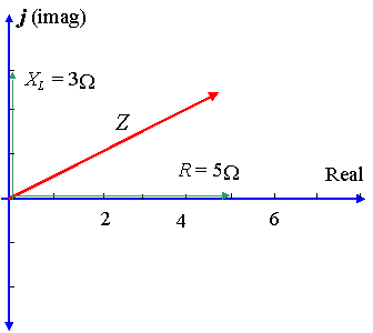
[h=3]Example 1[/h] A circuit has a resistance of 5 Ω\displaystyle{5}\ \Omega5 Ω in series with a reactance across an inductor of 3 Ω\displaystyle{3}\ \Omega3 Ω. Represent the impedance by a complex number, in polar form.
ap1.gif

Show answer
Image285.gif

In this case, XL=3 Ω\displaystyle{X}_{{L}}={3}\ \OmegaX​L​​=3 Ω and XC=0\displaystyle{X}_{{C}}={0}X​C​​=0 so XL−XC=3 Ω\displaystyle{X}_{{L}}-{X}_{{C}}={3}\ \OmegaX​L​​−X​C​​=3 Ω.
So in rectangular form, the impedance is written:
Z=5+3j Ω\displaystyle{Z}={5}+{3}{j}\ \OmegaZ=5+3j Ω​
Using calculator, the magnitude of Z is given by: 5.83\displaystyle{5.83}5.83, and the angle θ\displaystyle\thetaθ (the phase difference) is given by: 30.96∘\displaystyle{30.96}^{\circ}30.96​∘​​.
So the voltage leads the current by 30.96∘\displaystyle{30.96}^{\circ}30.96​∘​​, as shown in the diagram.
Presenting Z as a complex number (in polar form), we have:
Z=5.83∠30.96∘ Ω\displaystyle{Z}={5.83}\angle{30.96}^{\circ}\ \OmegaZ=5.83∠30.96​∘​​ Ω.
Get the Daily Math Tweet!
IntMath on Twitter


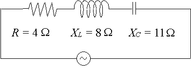
[h=3]Example 2(a)[/h] A particular ac circuit has a resistor of 4 Ω\displaystyle{4}\ \Omega4 Ω, a reactance across an inductor of 8Ω\displaystyle{8}\Omega8Ω and a reactance across a capacitor of 11Ω\displaystyle{11}\Omega11Ω. Express the impedance of the circuit as a complex number in polar form.
Show answer
ap2.gif
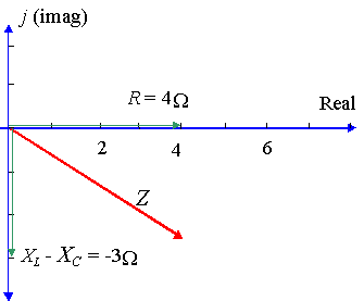
In this case, we have: XL−XC=8−11=−3 Ω\displaystyle{X}_{{L}}-{X}_{{C}}={8}-{11}=-{3}\ \OmegaX​L​​−X​C​​=8−11=−3 Ω
Image286.gif


So Z=4−3j Ω\displaystyle{Z}={4}-{3}{j}\ \OmegaZ=4−3j Ω in rectangular form.
Now to express it in polar form:
Using calculator, we find r=5\displaystyle{r}={5}r=5 and θ=−36.87∘\displaystyle\theta=-{36.87}^{\circ}θ=−36.87​∘​​.
[NOTE: We usually express the phase angle (when voltage lags the current) using a negative value, rather than the equivalent positive value 323.13∘\displaystyle{323.13}^{\circ}323.13​∘​​.]
So Z=5∠−36.87∘ Ω\displaystyle{Z}={5}\angle-{36.87}^{\circ}\ \OmegaZ=5∠−36.87​∘​​ Ω
Easy to understand math videos:
MathTutorDVD.com


[h=2]Interactive RLC graph[/h] Below is an interactive graph to play with (it's not a static image). You can explore the effect of a resistor, capacitor and inductor on total impedance in an AC circuit.
[h=3]Activities for this Interactive[/h]
  1. First, just play with the sliders. Drag the red dot left or right to vary the impedance due to the resistor, R\displaystyle{R}R, the blue dot up or down to vary the impedance due to the inductor, XL\displaystyle{X}_{{L}}X​L​​, and the green dot up or down to vary the impedance due to the capacitor, XC\displaystyle{X}_{{C}}X​C​​.
  2. Observe the effects of different impedances on the values of XLXC and Z.
  3. Observe the effects of different impedances on θ, the angle the black line makes with the horizontal (in radians).
  4. Consider the graphs of voltage and current on the right of the interactive. Observe the amount of lag or lead as you change the sliders.
  5. What have you learned from playing with this interactive?
[h=3](Interactive graph in link here)

Example 2(b)[/h] Referring to Example 2 (a) above, suppose we have a current of 10 A in the circuit. Find the magnitude of the voltage across
i) the resistor (VR)
ii) the inductor (VL)
iii) the capacitor (VC)
iv) the combination (VRLC)
Show answer
i) | VR | = | IR | = 10 × 4 = 40 V
ii) | VL | = | IXL | = 10 × 8 = 80 V
iii) | VC | = | IXC | = 10 × 11 = 110 V
iv) | VRLC | = | IZ | = 10 × 5 = 50 V
 

mbrooke

Batteries Included
Location
United States
Occupation
Technician
Here's a set of line currents established using phase currents (also included).

Van@0°
Vbn@-120°
Vcn@-240°

Ia = Iab + (-Ica) = 14.142V@-351.8699°
Ib = Ibc + (-Iab) = 13.601V@-126.0274°
Ic = Ica + (-Ibc) = 10.817V@-236.3099°


Iab = 8.602V@-324.4623°
Ibc = 6.083V@-99.4623°
Ica = 7.616V@-203.1986°

View attachment 17306


This might help if a interactive visualization is needed:


http://stevenblair.github.io/seq/
 
Status
Not open for further replies.
Top