JimmysLimeade
EE Student & PV Design
- Location
- Utah
- Occupation
- PV Design
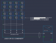
Hi, I am working on a DC side only design where they want to utilize the CE+T Stability 30C3. They are using 2 of those converters with 120 480W modules. My plan right now is to do 4 strings of 15 modules in series (totals to 804V) and then connect those in parallel (I dont really know the best way to do this so suggestions would be helpful) to hit 45A. Each converter has a maximum input of 1000V and 60A on the DC port which is why I decided to do it that way, but I need to know if I was correct in my reasoning here or if I need to fix it.
Another issue I am having is the grounding for this system. I am at a complete loss with this whole grounding document I attached below, it seems like none of the scenarios really fit what I need and I dont know how to properly adapt my system to be grounded correctly. Ive been looking into the negative ground referenced monopole option which would make the most sense to me, but I dont know how to best show that in my diagram.
I have been using a document from CE+T to base my initial design on but its somewhat lacking in detail of how to ground.
Sorry for all the questions, I just want to make sure I get everything here right.