Code reference

Status
Not open for further replies.

Vinniem

Senior Member
Location
Central Jersey
Need help finding a code reference.

Where does it say if you run 2 seperate circuits in the same device box, you have to seperate it with a barrier.

Thanks for the help
 
That's not what it says exactly.

What it says is. 404.8(B) A snap switch shall not be grouped or ganged in enclosures with other snap switches, receptacles, or similar devices, unless they are arranged so that the voltage between adjacent devices does not exceed 300 volts, or unless they are isntalled in enclosures equipped with permanently installed barriers between adjacent devices.
 
switch separation

switch separation

That rule only applied to separate 277/480 volt lighting if you had more than I ckt in switch box you are supposed to use barriers between switches where you can get 480 between them. This has been in effect for almost 20 yrs as far as I can recall. have hardly ever seen it done in the field except where I did original install and or find annother foreman capable of ordering the right parts.
 
celtic said:
Would putting two 277v circuits in the same box on the same phase require a barrier?


No, since the voltage between them would be zero, which is less than the 300 volts required for the barrier rule to apply.
 
quogueelectric said:
That rule only applied to separate 277/480 volt lighting if you had more than I ckt in switch box you are supposed to use barriers between switches where you can get 480 between them.

Depending on what phases on each side of a transformer are connected to the individual devices, you can have more than 300 volts between a 277v circuit and a 120v circuit.

1008709181_2.gif


Roger
 
The more important lesson

The more important lesson

Is it is a bad idea to mix systems from different panels. Try to make it idiotproof for those who are not properly trained It makes it harder for them to create problems when they have to assemble a violation on thier own.
 
quogueelectric said:
Is it is a bad idea to mix systems from different panels.

Not IMO.

quogueelectric said:
Try to make it idiotproof for those who are not properly trained It makes it harder for them to create problems when they have to assemble a violation on thier own.

If they are not properly trained they aren't qualified to be working on it, and no matter how hard you try, you will find an idiot that is better than your efforts.

Roger
 
barriers

barriers

By the way dont forget to ground that switch when you reinstall and good luck getting the barrier in unless you drill and tap a new hole on the other side of the barrier how much did you get for this switch anyway??
 
quogueelectric said:
good luck getting the barrier in unless you drill and tap a new hole on the other side of the barrier

Why would you have a hard time installing a barrier in a box and why would you want to drill and tap a hole for a self grounding type switch?

As an aside, if each conduit had an EGC installed only one would be needed to bond the box, the other could directly connect to a device on its side of the barrier.

If you have a problem doing this type of installation then by all means don't do it, but it is not dangerous if installed in a code compliant manner and it is a common installation, we do it frequently.

Roger
 
pic grounding yolk missing and one ground wire no barrier slots

pic grounding yolk missing and one ground wire no barrier slots

I personally have no problem installing this scenario contrary to your suggestion however there is no self grounding strap on the switch in the picture You provided . How you ended up going this far with this rediculous thread on an estimating forum I dont know( Moderator please) And when I qualified my statement I said that it was in efect about 20 years do you know the exact language and date that it was written in the code book around 1991 the code is constantly changing and being rewritten do you have a copy of all the old code books and the time to look this up and this is not the only answer to his question. There are other reasons to install bariers and I havent seen anyone post any other sugestions Is this jump all over the new guy week??
 
What is your point, and who is jumping on anybody, how do you know the switch is not a self grounding type switch, and the big question is, why are you upset?

The illustration is the property of the owner of this forum and it is correct, the fact is, the OP was simply asking for the Code Reference and you did not provide it.

I don't know why you think this is a "ridiculous thread", it is a real question that was answered by John in the first reply and simply turned into a discussion. If you truly think it's ridiculous then just don't participate when the discussion go beyond where you think it should end.

As far as the thread being in the Electrical Contracting and Estimating/Management forum, it could be due to estimating the material and labor, if I thought it was in the wrong forum I would move it.

BTW, I have code books back to 78 and a jump to 47

Roger
 
Last edited:
quogueelectric,
How you ended up going this far with this rediculous thread on an estimating forum I dont know( Moderator please)
Maybe we should have moved the question as it is a code question, but the answers are directly related to the question.
There are other reasons to install bariers and I havent seen anyone post any other sugestions Is this jump all over the new guy week??
The question was not about "other reasons" to install barriers...it was about the code requirement to install a barrier.
however there is no self grounding strap on the switch in the picture
None is required....see 404.9(B)(1).
Don
 
roger said:


I have an intermediate theory edumacation and I can not figure out how there is a difference of potential of 380volts between a 277v switch and a 120v receptacle in this graphic.

I know there are many variables to consider, but I would appreciate a brief explanation.

thanks

ibew441dc
 
The 380 volts comes from the fact that both systems are grounded systems and both are 3 phase systems. If you add 120 volts of A phase from one system with 277 volts from B or C phase of the other system you will come up with the 380 volts. The 2 voltages will be 120 degrees from each other and have to be added vectorially.
 
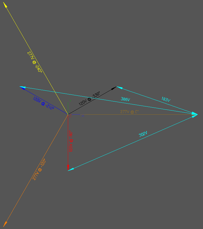
Note my above post is not correct, the voltage between one phase of the 480/277 volt system and a different phase of the 208/120 volt system would be ~356 volts if there is a 120 degree difference. In most cases the 208/120 volt system would be supplied by a delta/wye transformer that would have its primary connected to the 480 volt supply. In this case there would be an additional 30 degree phase shift from the delta wye transformer and if this phase shift is positive, there will be a 150 degree difference between A phase of one system and B phase of the other system. This would result in ~385 volts between the ungrounded conductors. If the phase shift was negative, there would be ~301 volts. The resultant voltage is found by using the rule of cosines to add the voltage vectors.
c^2 =a^2 + b^2 -2abCOS(angle)
c^2= c squared
c is the resultant voltage
a is 120 volts
b is 277 volts
Don
 
don_resqcapt19 said:
Note my above post is not correct, the voltage between one phase of the 480/277 volt system and a different phase of the 208/120 volt system would be ~356 volts if there is a 120 degree difference. In most cases the 208/120 volt system would be supplied by a delta/wye transformer that would have its primary connected to the 480 volt supply. In this case there would be an additional 30 degree phase shift from the delta wye transformer and if this phase shift is positive, there will be a 150 degree difference between A phase of one system and B phase of the other system. This would result in ~385 volts between the ungrounded conductors. If the phase shift was negative, there would be ~301 volts. The resultant voltage is found by using the rule of cosines to add the voltage vectors.
c^2 =a^2 + b^2 -2abCOS(angle)
c^2= c squared
c is the resultant voltage
a is 120 volts
b is 277 volts
Don

Don are you possible suggesting that the 380volts in the graphic is incorrect?

thanks
ibew441dc
 
ibew441dc said:
Don are you possible suggesting that the 380volts in the graphic is incorrect?

thanks
ibew441dc

It is not only possible it is a fact.

See the resultant voltages in the illustration below posted by Smart $ from this thread


277120voltages.gif


It is not only a 277 volt phase to another 277 volt phase that will give you 300 volts or more between conductors.

Notice there are two possible combinations of single primary to secondary phases which will be above 300v

Roger
 
Vectorial drawing is still wrong

Vectorial drawing is still wrong

If the low voltage transformers are fed from the high voltage system then the 3 phases will be in the same time voltage plane. For example when A phase of the high voltage is peaking the A phase of the low voltage will also be peaking putting aside the magnetic transfer led or lag of the transformer. So if A phase high voltage peaks at 120 A phase low voltage also peaks at 120 then both b phases at 240 and both c phases at 360/0
 
Status
Not open for further replies.
Top