- Location
- Tennessee NEC:2017
- Occupation
- Semi-Retired Electrician
Is it common to run the 120V coil, A2 (neutral) through the NC contacts on an overload? Why would you not run the A1 through the NC contacts? Does it make a difference?
Yes, that is normal, and is how Ugly's shows starters are wired. The biggest difference is if the OL contacts were before the coil, that is not how you would expect it to be. It does seem odd to have a circuit designed that "opens the neutral."Is it common to run the 120V coil, A2 (neutral) through the NC contacts on an overload? Why would you not run the A1 through the NC contacts? Does it make a difference?
This usually the case with NEMA motor starters that have the OL control contact and the aux holding contact control wires prewired from factory.My theory is that the OL contacts are on the “common” side from the factory so that people in the field won’t inadvertently mis-wire something in the control circuit (bypassing the OL contacts) since all of the control connections will be on the “hot” side.
Bear in mind I have no idea what is common for lifeboat winch motors but I'd have to say that a lifeboat winch possibly could be an intermittent duty motor, and overload protection rules are not the same as for continuous duty motors, often you don't even need an overload protector in many I have been involved with. Vehicle hoists with hydraulic pump is one the more common ones I see.I've seen motor overide circuits that will bypass the OL contacts in case a motor trips and you have a suspended load that HAS to be let down. Lifeboat winches are one application.

Any two lines works. You know that as well.I say no for 120 v ac
I teach A1/ A2 based on 1,2,3,4 which is left side of ladder moving right with the grounded conductor right side A2 through overloads. Code teaches us left to right top to bottom so this falls in line with the rest of the teaching.
1 ends at 1, 2 ends at 2
Makes trouble shooting a piece of cake
This also help them understand all stop in sieres. 1a,1b etc before 2.
It add meaning to the madness.
Commentary:
Now if it did not run (grounded conductor) though OL,NC you could run into an issue
The reason is In case the the grounded conductor get damaged and makes a ground contact.
The chances are lower for that one short piece of wire.
Another reason to use line to line with fuses on both lines when it really maters. Then it takes that short wire out of the hazard analysis.
Imagine an e- stop with a start stop using a grounded conductor for 1,2,3 with the ungrounded running thru OL, NC. Greater chance of the control circuit being out of control if a wire makes a ground connection.
Ugly was mentioned and ask your self why L-3 instead of L-2 for line to line control circuit in 3- phase.
I do see your point. With the OL last, the coil is sourcing and the OL is sinking. The other way, the OL is sourcing and the coil is sinking. For those scratching their heads, consider what happens if the wire between them grounds out. In the first case the coil could pull in when the OL is actually tripped. In the second case, you get a blown fuse when there is a ground. Or would this all be an argument to have an ungrounded control circuit?I say no for 120 v ac
I teach A1/ A2 based on 1,2,3,4 which is left side of ladder moving right with the grounded conductor right side A2 through overloads. Code teaches us left to right top to bottom so this falls in line with the rest of the teaching.
1 ends at 1, 2 ends at 2
Makes trouble shooting a piece of cake
This also help them understand all stop in sieres. 1a,1b etc before 2.
It add meaning to the madness.
Commentary:
Now if it did not run (grounded conductor) though OL,NC you could run into an issue
The reason is In case the the grounded conductor get damaged and makes a ground contact.
The chances are lower for that one short piece of wire.
Another reason to use line to line with fuses on both lines when it really maters. Then it takes that short wire out of the hazard analysis.
Imagine an e- stop with a start stop using a grounded conductor for 1,2,3 with the ungrounded running thru OL, NC. Greater chance of the control circuit being out of control if a wire makes a ground connection.
Ugly was mentioned and ask your self why L-3 instead of L-2 for line to line control circuit in 3- phase.


All NEMA starters come wired that why unless you specify otherwise. I only did one project in my career when the engineer would not permit the overload relay contact to be in the grounded conductor side of the circuit.Is it common to run the 120V coil, A2 (neutral) through the NC contacts on an overload? Why would you not run the A1 through the NC contacts? Does it make a difference?
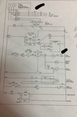
That's correct and the way I see it. Most of the schematics that I have seen actually say A1 and A2, this one did not and I wanted to make sure.It looks like the grounded conductor for M1 ( motor 1) coil runs through NC of O-1 ( over load 1)
Grounded conductor(X2) to 95. 96 to A2. 95/96 NC overload block.
2 to 2 right side of ladder.
My copy a little blurry hope I read it correctly.
It darn well better be wired like shown. I am the one that designed the thing and approved the drawing! (Just kidding). But yes, that is the normal way and what I would do with the motor control. But I would also include a lighted e-stop first thing after the fuse.Look at this schematic and go down about half way. Start at the door safety LS-1 and over to the "wash/off/rinse switch.
How would you wire this through M1 and OL?
If I were designing it I either put the OL as first thing in the line or first thing before the coil.Look at this schematic and go down about half way. Start at the door safety LS-1 and over to the "wash/off/rinse switch.
How would you wire this through M1 and OL?
I would first do a risk analysis based on the operation of the machine.It darn well better be wired like shown. I am the one that designed the thing and approved the drawing! (Just kidding). But yes, that is the normal way and what I would do with the motor control. But I would also include a lighted e-stop first thing after the fuse.