Combo panel transfer switch solution

Status
Not open for further replies.
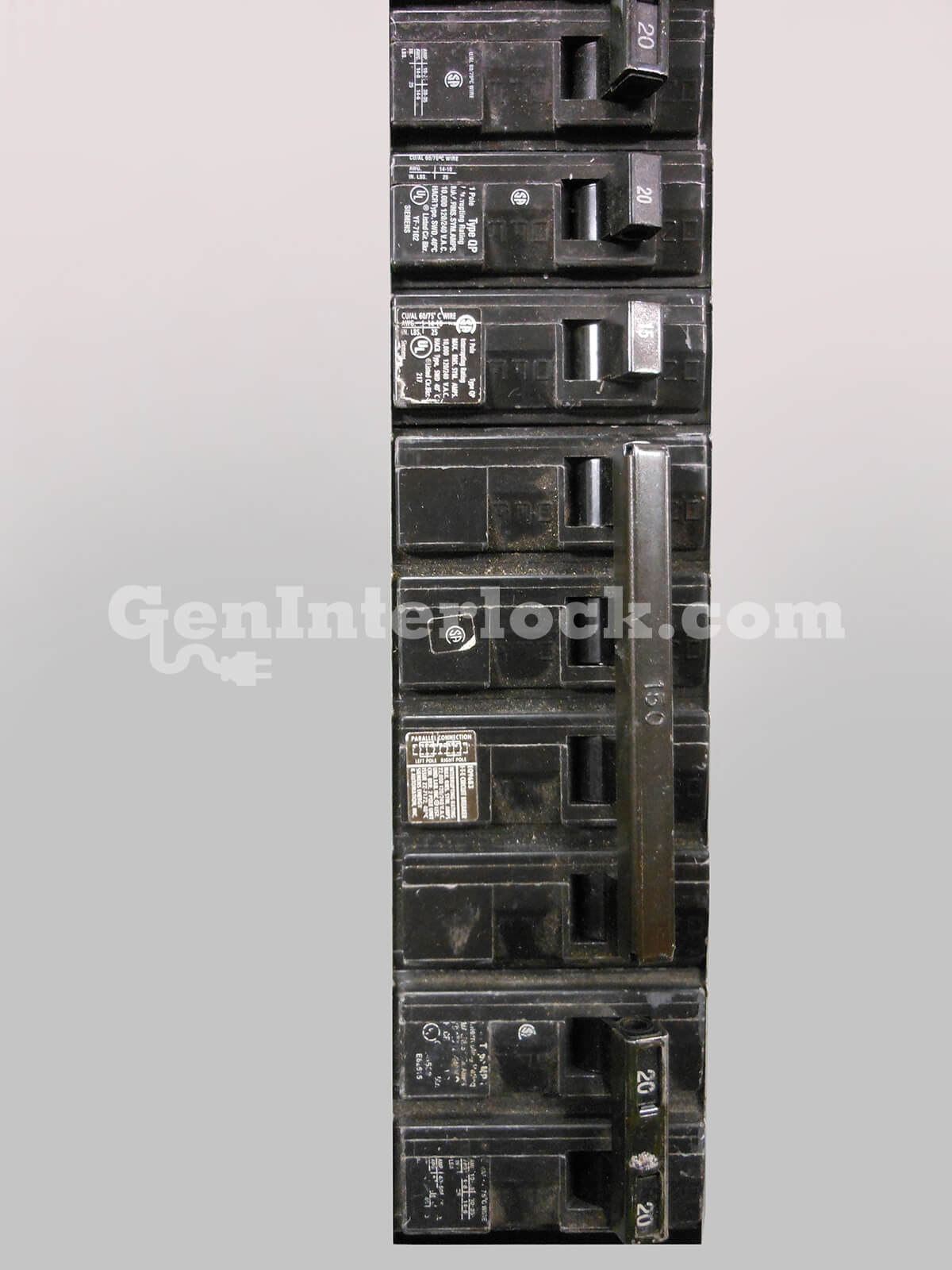
Looking for ideas on the most practical solution to connect a transfer switch to this Siemens combo panel.

The mains from the street come in to the bottom and outlet of the meter connects to the 200 amp main breaker in the panel.

Looking for an approved solution to connect to the new transfer switch without replacing the main panel.
65FD30CE-FEFE-42FF-BAB2-0C1C6D80EE29.jpeg
Thanks.
 
There are interlocks that are made for various makes of panels, check out what is offered here.


BTW, that SQ D HOM is not UL classified to be used in any competive panel.
Thanks but I am looking for a solution that will allow me to install an automatic transfer switch. The mains feeding the inlet side of the 200a main will have to be interrupted to accomplish this.
 
Intercept the service conductors ahead of the service disconnect, to a service rated ATS, and from load side ATS back to combo panel
 
Thanks but I am looking for a solution that will allow me to install an automatic transfer switch. The mains feeding the inlet side of the 200a main will have to be interrupted to accomplish this.
Intercept the service conductors ahead of the service disconnect, to a service rated ATS, and from load side ATS back to combo panel
I was hoping the JHA would approve that. Planning on intercepting the feeders with insulated splices, run conductors over to the
service rated ATS, and back to the meter.
 
Intercept the service conductors ahead of the service disconnect, to a service rated ATS, and from load side ATS back to combo panel
POCO would have to approve that, along with the inspector.
Not much you can do with a meter/main other than adding a panel or replacing the panel.
Problem multiplies itself in the OP's case as everything appears to be flush mounted.

ETA: Me and Hillbilly posted at the same time!
 
POCO would have to approve that, along with the inspector.
Not much you can do with a meter/main other than adding a panel or replacing the panel.
Problem multiplies itself in the OP's case as everything appears to be flush mounted.

ETA: Me and Hillbilly posted at the same time!
Yeah, it’s not gonna be fun. Planning on putting a crew cover can below the meter side of the panel inside the wall below to pull the wires through, and gutter across to the ATS. The scc will be accessible with an access panel on the inside.
 
It's my understanding that the OP's method violates rules about field modifications to listed assemblies.
 
How are you planning to add a can below the meter section? Those are PG&E's conductors and you must keep the sealed pull section intact. Technically you have committed a felony by opening that section and installing the CT's there. A PG&E T-Man or Line Crew would probably cut your service off in the street if they saw that. Also if you were to put a transfer switch before the meter you would be paying PG&E for the electricity you generate.

There is no way to intercept the wiring between the meter and the loadcenter interior without voiding the listing of the panel. If I was inspecting it you would bet replacing the panel if you tried it.

The easiest way would be to install a 100 amp breaker to feed the transfer switch and move the backup loads to a separate panel connected to the transfer switch. I highly doubt you are going to be able to install a residential generator that will supply more than 100 amps in California.
Your solution is the simplest one, the semi flush panel & no compliant way to modify that panel makes things harder.
 
Status
Not open for further replies.
Top