hey guys, we have a project upcoming, computer lab, i am unclear on the calculated load assesment, can someone give some input on this.
33 computers 3.0 amp ea = 99a
1 server ? =05a
2 laser printers 10ea =20a
#1. 124a, would you agree this is the calculated load?
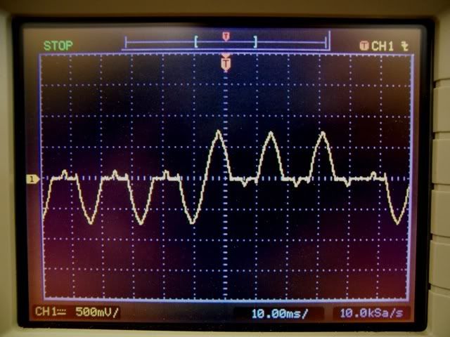
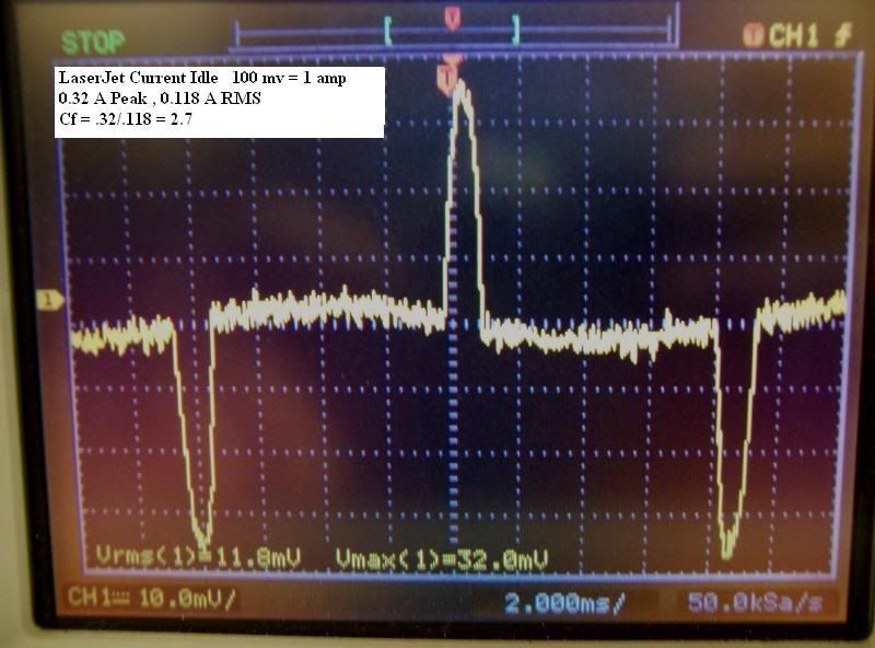
#2. i put an amprobe on a circuit supplying 6 computers that were rated a 5.0 ea the reading was approx 8 amps, the computers were not being used , but were on ,why would it be so low if the 6 are rated at 5.0 amp each? anyone
33 computers 3.0 amp ea = 99a
1 server ? =05a
2 laser printers 10ea =20a
#1. 124a, would you agree this is the calculated load?
#2. i put an amprobe on a circuit supplying 6 computers that were rated a 5.0 ea the reading was approx 8 amps, the computers were not being used , but were on ,why would it be so low if the 6 are rated at 5.0 amp each? anyone