FaradayFF
Senior Member
- Location
- California
Gents,
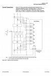
For a three-phase protection current transformer, is it OK to jumper together polarity marked leads to create a Y and bring out non-polarity conductors to a protective relay? I recently saw a configuration depicted in the attached sketch where the CT upstream of protected equipment had the polarities connected together, which threw me off, since the CT has to be properly installed & wired in the field to function properly in a scheme.
Please provide your insight. The CT configuration on the left is what I'm used to seeing ..
Thanks,
FaradayFF