aftershock
Senior Member
- Location
- Memphis, TN
Im doing a 400 amp service for an addition. The POCO issues our meter sockets and when doing an addition we have to turn in a load. Apparently if the load exceeds 48Kw then we have to use CT's. I have never installed a service in this manner.
Since my service wires will not go through a meter and I will be having 2-200 amp panels, can I just run a mast pipe from the top of each panel or will I have to parallel the service into a trough and splice from there into each 200 amp panel? Is there a code section in the NEC that addresses this?
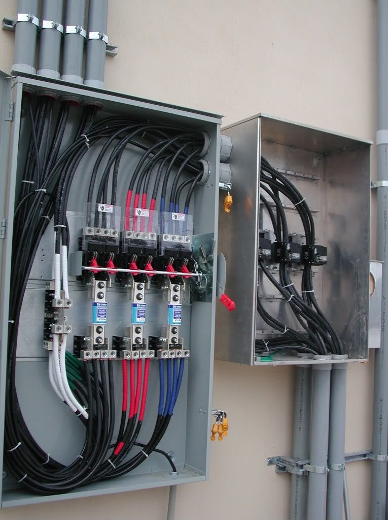
Another question: Is there a wiring diagram I can obtain that shows the wiring from the CT can to the donuts?
Since my service wires will not go through a meter and I will be having 2-200 amp panels, can I just run a mast pipe from the top of each panel or will I have to parallel the service into a trough and splice from there into each 200 amp panel? Is there a code section in the NEC that addresses this?
Another question: Is there a wiring diagram I can obtain that shows the wiring from the CT can to the donuts?