D-line Contactors

Status
Not open for further replies.

oldno7

Member
I have a situation on a machine that requires some special control wiring. On the machine itself, they added a blower motor that needs to run only when certain low voltage 24 vdc valves are energized. There is a control box that has all the control blocks and wiring, and that is where I will be installing my D-line contactor/starter. Here is where I need a little help. I will bring my 480 volt 3 wire feed in to the control box, wired to a 3 pole contactor and then to the moter. I have 3 separate 24 vdc valves that when they are energized (they all run at separate times, never together) the blower motor has run at that same time. The contactor has A1 wich is my positive, A2 wich is the negative, and a NC and a NO.
I'm thinking there must be an auxiliary contact to add to make this work, because of the 3 control wires. Any Suggestions?

Thanks
Brandon
 
Hopefully that 3P contactor also has an overload connected :grin:

Aside from needing to know the coil voltage, as bstoin asked, what is the amount of current necessary to hold in the coil? What voltage sources are available in the control box? Is the 24VDC source located in the control box or remote, and is there an excess of available current from the supply? What controls the 24VDC solenoid valves: 1) Relays—configuration: poles & throws or # of NO and NC contacts? ...any available poles or identical to solenoid control contacts? 2) PLC—internal or remote? ...output block type? ...any available outputs in control box? ...reprogramming of PLC available or not readily? 3) Manual operator switches or overides? ...contact ratings? ...any available parallel contacts or can some be added (i.e. stacked)? These are some of the design considerations. There easily may be more.

Yes, there is a good chance an auxiliary contactor (relay) will need to be added.

Anyway, making the motor starter kick in is easy. Determining how to kick it in without overloading any of the control circuits AND not having all three valves operate concurrently is a little harder...quite a bit harder from where I'm sitting :roll:

Got milk? ...oops, wrong question :grin: Got a picture (and/or schematic)? If so, I'd be more than willing to take a look at it if you can get it in or convert it to a common digital format (dwg, dxf, dwf, pdf, jpeg, gif, etc.). If you can't or don't know how to host it on a web server and provide a link here, let me know via private message and I'll provide one of my email addresses.
 
The coil voltage is 24vdc. I'll try to send some pictures of what I have to see if that can clarify the application.

Thanks very much,
Brandon
 
if you can't reprogram the PLC, you could use 3 ice cube relays. One relay in parallel with each valve. Series your contactor coil power through N/O contacts on each relay. When all relays are closed, your contactor will actuate.
 
romexking said:
if you can't reprogram the PLC, you could use 3 ice cube relays. One relay in parallel with each valve. Series your contactor coil power through N/O contacts on each relay. When all relays are closed, your contactor will actuate.
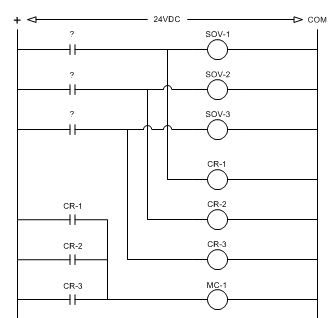
I gathered the blower motor needs to operate whenever any one of the valves operate, and no two valves operate concurrently. In the scheme you propose the NO contact of each relay would need to be in parallel with the motor starter coil, as such:

d-line1.gif


However, what if the valves are powered through relays which have spare contacts? The additional relays may be unnecessary.
 
I'm sorry, I thought that they ALL had to be on for the motor to run. If any ONE has to be on, yes aux. contacts on each valve contactor can be run in parallel with each other using the coil power source for the 480 volt contactor. Smart $'s schematic looks correct, as he mentioned, you will need to check the power consumed on the control circuit. The capacity of the original control circuit may not be enough to pull in the 480 volt contactor.
 
If your coil for the motor starter is 24 volt, then all you need to do is tie the three solenoids to the coil (together)...that way if any become energized they close the contact and run the motor.
 
bstoin said:
If your coil for the motor starter is 24 volt, then all you need to do is tie the three solenoids to the coil (together)...that way if any become energized they close the contact and run the motor.
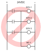
Afraid not. That not only energizes the motor starter coil, it also energizes all three solenoids at the same time when only one of the three is supposed to be energized.

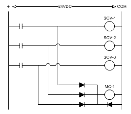
You could prevent simultaneous energization of solenoids through the use of diodes, but we don't have enough information to determine the current available on the solenoid circuits and we are not sure how much current is required to pull in and hold the motor starter's contactor.

d-line2.gif
 
Last edited:
Smart $ said:
Afraid not. That not only energizes the motor starter coil, it also energizes all three solenoids at the same time when only one of the three is supposed to be energized.
Unless you use isolating diodes, which you can since you're using DC. Need a schematic?
 
The normally open contacts on each contactor, which are already in place, will do the trick. Wire all three in paralell to each other and then in series with MC-1.

Wow, I like that diode configuration, but the NO aux contacts are already in place.
 
LarryFine said:
Unless you use isolating diodes, which you can since you're using DC. Need a schematic?
Sorry about making your post appear superfluous, Larry. I hit the submit button and posted prematurely, so I created the schematic while in edit mode without refreshing my browser display. The delay is because I did it between watching segments of "Lost".
 
thunder15j said:
The normally open contacts on each contactor, which are already in place, will do the trick. Wire all three in paralell to each other and then in series with MC-1.

Wow, I like that diode configuration, but the NO aux contacts are already in place.
Just what NO contacts are you referring to?

In the last diagram there are only three and they are not auxiliary contacts. They are either NO contacts on individuallyy powered relays, or NO contacts on a PLC relay-output block. In addition, we haven't even established if the solenoids are operated through contacts, though typically they would be.

Let me assure you, if the solenoids are contact driven, you cannot simply connect all three outputs together to energize the motor starter's contactor...

d-line3.gif
 
hillbilly said:
What purpose does that 4th diode (the one that's shown under the motor contactor coil) have?
Just curious
steve
To counter the effect of magnetic hysteresis. [edit to add... at least that's what I've always been told :grin: ]
 
Last edited:
Status
Not open for further replies.
Top