Detect direction of motor shaft

Status
Not open for further replies.
Hi again...

I have been trying to find out cost effective ways to externally detect the direction in which the motor shaft is moving. the direction sensor should be able to give me a pulse 0 or 1 based on which direction the motor shaft is moving. The pulse should be good enough to drive a transistor or small electronic circuit.

the sensor should sense the direction within one rotation of the shaft. I can use a small magnet or led connected to the shaft to help the sensor detect the direction. can any one tell me of any ready to use ic's or sensor's for this..

i have found the following HAL effect ic's on the net...a) micronas 710/730 and Allegro A 3423. however i dont know of the cost and the support for these ic's is very limited where i stay..

Can i use other hal effect ic's for detecting direction of motion?

thanks a lot...

Try this link

I've used Red Lion products in the past, and it's really good equipment.

You can mix and match components to do about anything.

http://www.alliedelec.com/search/se...Primary&Ntt=RED+LION&Source=&sid=12023458AC51

steve
 
090320-1256 EST

starcrossed:

Is this a one-shot or production product application? How many are needed? What is meaning of cost effective?

What is the application? Maximum RPM? Why within one revolution? What is done with this information?

.
 
The rpm will be between 6000 to 12000, the motor is going to be a small motor dc motor around 35- 40 mm dia and 30 mm lenght. by cost effectiveness i mean less than 1 usd.

I guess quadrature encoder will best shot...can you suggest some place where i can get circuit and schematic diagram...i believe i can use the d-flip flops for that..

also i thing the allegro A3423 works like quadrature encoder...am i right..?
 
Last edited:
The rpm will be between 6000 to 12000, the motor is going to be a small motor dc motor around 35- 40 mm dia and 30 mm lenght. by cost effectiveness i mean less than 1 usd.

I guess quadrature encoder will best shot...can you suggest some place where i can get circuit and schematic diagram...i believe i can use the d-flip flops for that..

also i thing the allegro A3423 works like quadrature encoder...am i right..?

Actually i am making a direction switch where the swich will run the motor in one particular direction the moment it detects motion in that direction. Like a manual cranking switch.

In my application, the motor will be moved externally by some force. now the moment the motor starts moving in one particular direction the sensor should detect it and activate a circuit that gives power to that same motor and the motor starts rotating full speed in that direction. like manual cranking of motors...

i was initially thinking of sensing the back emf produced by the motor. Every motor can act as generator. So moment the motor is externally moved by some force it will generate some voltage/current. however the problem is that this voltage and current are so small for initial few rotations that its impossible to use it to run any electronics. is there any way i can boost up this voltage to atleast 0.7 to 1 volt so that i can turn on a transistor switch??
 
090321-0639 EST

starcrossed:

An op-amp will give you the gain you need.

You might start with an OP27 and a gain of 1000. This will be too expensive for your final product, but good for experimenting. Try a 1 K input resistor, back-to-back 1N4148s for clamping, and a 1 M feedback resistor.

You will need a book on working with op-amps.

.
 
090321-0639 EST

starcrossed:

An op-amp will give you the gain you need.

You might start with an OP27 and a gain of 1000. This will be too expensive for your final product, but good for experimenting. Try a 1 K input resistor, back-to-back 1N4148s for clamping, and a 1 M feedback resistor.

You will need a book on working with op-amps.
Then you need the power supplies, a PCB to mount it all on, layout and tooling charges etc.
For 1$ US........
 
The rpm will be between 6000 to 12000, the motor is going to be a small motor dc motor around 35- 40 mm dia and 30 mm lenght. by cost effectiveness i mean less than 1 usd.

Under $1.00 US?

20301-2009-2-2ww-m.jpg


Hold the above device loosely by the point and touch motor shaft with the rubber end .... make mental note of the direction it moves. :wink:
 
Under $1.00 US?

Hold the above device loosely by the point and touch motor shaft with the rubber end .... make mental note of the direction it moves. :wink:
Might be a bit of a challenge to do that in 5ms or less.....
:wink:
 
Last edited:
I think this solution will work....

http://www.allaboutcircuits.com/worksheets/servos.html

All i need is a 0 or 1 depending on the direction in which the motor is moving..

a small perforated disk - INR. 5, 2 pairs of LED and sensors-INR 30, D FLIP FLOP-INR 10, couple of resistors -INR 5. Total around INR 50 - about 1$.

i am yet to try out the circuit though...but will try out and post the
responce...

even the solution of GAR will be around 1$,...
i am ofcource excluding the cost on the motor itself... ;-)


Lemme know your views...
 
Last edited:
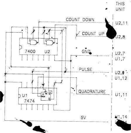
here is a picture of a drawing I made in about 1987 in my basement:

encoderquadrature-1.jpg


The smudges are ink from trying to unclog drafting pens.The drawing was made on a flat bed plotter that held eight pens of different colors. Man, I loved that thing.

My point in all of this is that there is a long way to go from posting a link that shows drawings of perforated discs, LED's, sensors, and chips to getting a working prototype. Longer still to a reliably performing "solution" .

From your last post , I got a kind of "see, you can too do this for a buck ", "rubbing your nose in it", feeling.

I don't want to discourage you, but whatever you try, you are probably not the first person to try it... and neither was I. I just didn't realize it at the time. I spent a whole bunch of time on stuff like this, that I probably should have spent on the floor with my kids.
 
All i need is a 0 or 1 depending on the direction in which the motor is moving..
Of what I understand of your project, won't you also need a "coding" for no motion. If you only have 0 and 1, then your circuit will likely tell the drive it is moving in one direction or the other and never at rest. I believe you have to move up to 2-bit detection coding if staying in the digital realm ;)
 
090322-1052 EST

starcrossed:

Following is what I have concluded is the logic you want:

1. Somehow the motor can be put to a zero RPM state. This may be by the removal of power until it is stopped.

2. When power is available to rotate the motor it does not rotate until it is given an initial mechanical rotation and then it is powered with full voltage to rotate in the direction of initial rotation.

3. Rotation will continue in the initiated direction until (1) above occurs.

I think your $1 concept is not feasible, but it can be a goal.

This will involve the op-amp previously mentioned to feed the following transistors.

Disregarding the cost goal the following should work. Two double pole output relays, one for each direction. When neither is energized the motor is depowered. One relay causes rotation in one direction. The other relay in the opposite direction.

Relay F (forward) is controlled by an NPN transistor. The base to emitter voltage has to be somewhat positive to energize the relay. This provides a dead zone near zero speed. There is inherent positive feedback in this system. Once the relay is energized the motor is driven faster in the direction started and this increases the signal to the transistor and thus the loop is held in the on state.

Relay R (reverse) is driven by a PNP transistor. Otherwise the operation is the same except rotation is in the opposite direction.

Note: the control circuitry as described uses a + and - supply.

This description is not a minimum cost system, but one that should work and allow evaluation of the system.

.
 
Status
Not open for further replies.
Top