Difference between Electrical Plan and Electrical Layout

Status
Not open for further replies.

cadpoint

Senior Member
Location
Durham, NC
I think it is a just word play, and bad at that.

Depending on a what exactly one is presenting should be called out according! JMO.

A plan could be alot of things, Site plan, floor plan, arrangement plan, englarge arrangement plan. but it truely, "Here's the plan encompassing the project".

A Reflected Ceiling Plan is as I was told at an Job (another life) was looking up not down from the floor called out.

The grey area is yes your looking down on an electrical plan!

A Single Line Diagram might get also be incorrectly called a Riser Diagram, but a Riser Diagram can done in with single line work, and notation...


A Single Line generally shows the internal aspects of the the wired application, a Riser is the bulk materail that has the objects connected!

I didn't even get in to sectional elevation (this is your line of sight) cut, Elevations, Section, Bubble's... etc

Clear as Mud ? ?

Enjoy
 
Last edited:

ohmhead

Senior Member
Location
ORLANDO FLA
Confused about the two name,do they have the same or another meaning?

Thank you.

God Bless...

Well a electrical plan is your contract drawnings by engineer and a electrical layout is your cad drawnings or construction drawnings Bim drawnings which show how you are going to do your underground or over head your actual layout of cordinated work of conduit routes and racks or raceways .

Which is something a electrical engineer cant do electricians only do layout work . Meaning we use the electrical plan and then route our conduits because a engineer doesnt do that for us.

We take each conduit to and from each electrical room and figure how we can get it from point a to point b the electrical plan only shows it on a oneline riser we must find the location to and from.
 

cadpoint

Senior Member
Location
Durham, NC
Well a electrical plan is your contract drawnings by engineer and a electrical layout is your cad drawnings or construction drawnings Bim drawnings which show how you are going to do your underground or over head your actual layout of cordinated work of conduit routes and racks or raceways .

The OP asked for clear defination of a title of a drawing, it doesn't take an engineer to make a bad drawing or a bad title, your statement is out of bounds to clearify any aspect of a discipline does to a drawings title, come on.

Which is something a electrical engineer cant do electricians only do layout work . Meaning we use the electrical plan and then route our conduits because a engineer doesnt do that for us.
....

I've had many conversations with an EE, he could care less of an electrican's route. If there paying attention minus value engineering, get'r done.

If they want to pay for Routing most clients don't, then go with the plan, or don't unless someone said Don't scale this Plan, otherwise do something of whats required and as is presented, then pay attention to the plan, arragement or detail, and read the notes...
 
Last edited:

ohmhead

Senior Member
Location
ORLANDO FLA
Well Cadpoint at our work place which is electrical construction we call a electrical plan a engineered contract drawning and a electrical layout is ours so whats your point . Our layout is CAD and BIM 3 d drawnings And we use a trimble to do our field points for all electrical layout from Auto cad .


Thats the way i see it contract drawnings are just a set of electrical plans we look at them correct them and revise them for the engineers then we layout our work to build it our way after all ther mistakes are found .

Thats about how i see it the OP asked a question and we answered it .

If you look at his profile hes a CAD tech so i think he knows what CAD is .
 

cadpoint

Senior Member
Location
Durham, NC
Well Cadpoint at our work place which is electrical construction we call a electrical plan a engineered contract drawning and a electrical layout is ours so whats your point . Our layout is CAD and BIM 3 d drawnings And we use a trimble to do our field points for all electrical layout from Auto cad .


Thats the way i see it contract drawnings are just a set of electrical plans we look at them correct them and revise them for the engineers then we layout our work to build it our way after all ther mistakes are found .

Thats about how i see it the OP asked a question and we answered it .

If you look at his profile hes a CAD tech so i think he knows what CAD is .

I don't care what your Drawings Title again the subject is the exact title of a drawing. How there are presented is a whole nother matter CAD drawings, or otherwise.

There is basically from an "engineered" IE paid for, Documents;
Design deveolop drawing DD's, Contract contruction, CC's and Contract Documents(Record Copy)CD's. Great

Maybe I got it order wrong per the initials ...

It is a three step process from an "Engineered" stand point, there are many variable of what a client wants and needs, and will pay for.
 
Last edited:

ohmhead

Senior Member
Location
ORLANDO FLA
Well Cadpoint on electrical drawnings we see lighting/ pages power/ pages fire alarm /pages com /data pages sound /pages security/ pages control/ pages lighting & fixture / schedules pages panel /schedules pages and the oneline power riser pages also the details pages grounding oneline /pages electrical room / pages data/ com room/ pages ect ect .

But i have never seen a page called a layout page .
 

charlie b

Moderator
Staff member
Location
Lockport, IL
Occupation
Semi-Retired Electrical Engineer
(layout) . . . is something a electrical engineer can't do; electricians only do layout work .
Oh yes we can, and sometimes we have to. On a recent project, I did the layout for a significant conduit run. Not all runs, but one in particular. I had to, because there was limited space to get from one floor to the next, and I had to coordinate the space usage with the mechanical and plumbing engineers.


Most of the time, my drawings will (as you suggest) only show the points at which electrical components are to be located, leaving the actual conduit routing to the electrician. But don't tell me I don't know how to do it.
 

charlie b

Moderator
Staff member
Location
Lockport, IL
Occupation
Semi-Retired Electrical Engineer
In my world, an "electrical plan" would show the entire floor as an architectural background, and I would place symbols for the locations of the electrical equipment (e.g., receptacles, luminaires, motors, panels, disconnect switches). I use the phrase "electrical layout" in the context of an enlarged plan that shows only a single electrical room, and that shows the locations of panels within that room, along with the space reserved for working clearance.
 
Oh yes we can, and sometimes we have to. On a recent project, I did the layout for a significant conduit run. Not all runs, but one in particular. I had to, because there was limited space to get from one floor to the next, and I had to coordinate the space usage with the mechanical and plumbing engineers.

Most of the time, my drawings will (as you suggest) only show the points at which electrical components are to be located, leaving the actual conduit routing to the electrician. But don't tell me I don't know how to do it.

In many cases it SHOULD be done. Any commercial or institutional facility and definetly industrial facility, the electrical right-of-ways are established, along with plumbing/piping, HVAC etc. This reserves the SPACE which is available to each discipline.

Definetly underground cable and conduit runs SHOULD be documented and installed according to the plans.

Do you think the Dubai Tower was done by homeruns?
 

ohmhead

Senior Member
Location
ORLANDO FLA
In my world, an "electrical plan" would show the entire floor as an architectural background, and I would place symbols for the locations of the electrical equipment (e.g., receptacles, luminaires, motors, panels, disconnect switches). I use the phrase "electrical layout" in the context of an enlarged plan that shows only a single electrical room, and that shows the locations of panels within that room, along with the space reserved for working clearance.

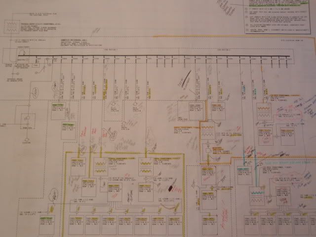
Well Charlie your one of a few! Here is a oneline power riser sheet typical commercial plan we see the rooms numbers on the drawing of each room we see the feeder sizes and conduit sizes but they do not tell us how to get from point a to point b physically do you see what iam getting at .

That takes months of planning elevations routes other trades structual mechanical plumbing piping overhead and underground never seen a engineer do it ever !


This was one oneline of 6 risers lots of gear .

P1010047_01-1.jpg


We spend months laying out rooms because the gear never fits in the rooms per the engineer plans the gear can be 5 different types .
This is a normal issue on each job we have to figure how many conduits go to room A from room B .

Then duct banks and major conduit runs must be layed out to structural & art and elevations in build and out of building on cad or bim we check mechanical & plumbing and work out the buggs with other trades.

Each week we have meetings on site and use auto cad to corrdinate these issues we do large projects the only time we get a route is when we do a power plant then electricians have a planned route by electrical engineer but commercial is not so we do it every year .

PLAN is drawnings but layouts our what we submit to engineer on cad and asbuild the job to these per contract its in our contract to do cad and work with each trade and show our work before we digg or start work on site .

Did i miss something do other companys go by the prints totally i dont see how this is how we do major projects it takes months of planning before we start work ?

A normal job for us is 2.5 years and 4 months of planning on the electrical .
 
Last edited:

iwire

Moderator
Staff member
Location
Massachusetts
Confused about the two name,do they have the same or another meaning?


In my area the 'E' prints show the circuitry and a general idea of where the equipment will be.

On the other hand the 'A' prints will not show any circuitry but they will show specific locations of equipment.

So I guess you could call the E prints the plan and the A prints the layout.
 

charlie b

Moderator
Staff member
Location
Lockport, IL
Occupation
Semi-Retired Electrical Engineer
Ohmhead, most of the time I will not show any conduit routing. I only do that on large projects with complicated interfaces among disciplines.

Usually, I will have riser diagrams (like the one you showed), and floor plans (that show any panels that go into corridors), and enlarged floor plans (that show how to lay out panels inside electrical rooms). I would never leave that last thing to the electrician. I know you are capable. But I believe it to be my duty to prove that the number of panels I want to put into a room can actually fit into that room, and still have the required working clearance in front of each. I don't even have my CAD group do that work for me; I do my own layouts in CAD. That is because I will keep flipping things around and moving panels across the room and doing whatever is necessary to get things to fit.
 

cadpoint

Senior Member
Location
Durham, NC
As I've read here, the default dictionary for the NFPA is the Merriam Webster.

This is a link to what I believe is one in the same: www.merriam-webster.com

I say that because there is history and copy right protection "history" with the "names" and
the use of a Dictionary and word association with the name and a dictionary, I haven't chased it

I also like to use the Princeton dictionary;

http://wordnetweb.princeton.edu/perl/webwn

But more for style content!

Enjoy
 

ohmhead

Senior Member
Location
ORLANDO FLA
Ohmhead, most of the time I will not show any conduit routing. I only do that on large projects with complicated interfaces among disciplines.

Usually, I will have riser diagrams (like the one you showed), and floor plans (that show any panels that go into corridors), and enlarged floor plans (that show how to lay out panels inside electrical rooms). I would never leave that last thing to the electrician. I know you are capable. But I believe it to be my duty to prove that the number of panels I want to put into a room can actually fit into that room, and still have the required working clearance in front of each. I don't even have my CAD group do that work for me; I do my own layouts in CAD. That is because I will keep flipping things around and moving panels across the room and doing whatever is necessary to get things to fit.

Well Charlie with respect for you and all electrical engineers out there you are one exception to what is now. We have lots of issues today with corrections and were held to the letter if its a code issue or a wrong size feeder or breaker its on me so we go thur each project with care .

I know your are the designer and we respect that i didnt go to engineer school but sometimes i feel i should have .

I think today its fast turn over and no time is taken to look .

I have noticed in the last 10 years there is less prints on paper less paper but more computer generated printer plotter paper we get our drawnings from plotters and copie machines we email this and that .

Its a paperless world !!

Also auto cad its not what everyone thinks it makes mistakes we have a $ 40 ,000 dollar trimble and we use it to layout our elevated decks but if the program is off one day its down and it can be off by inches not good .

Heres a example of our high tech equipment if the trimble gets a reflection from a near building meaning glass reflection of sunlite in its station prism its off by inches to feet also sometimes the program fails and you dont know it .

What happen to the old string and plumb bob ?

I am old school and still do layout the old way with a string and a metal tape & plumb bob 6 ft level and a set of blue prints old transit & site level .

But today you better be using auto cad or you not going to compete with others and all the construction managers today like 3 d layouts of our work i dont see the reason we put it on paper give it to the cad people and they input it in computer but the electrician still needs to lay it out on paper so its a long road to final layout .

Its just funny sorry if i go off a bit i get going and cant stop .

I hope Cadpoint is not upset with me we just do things or call things differently its all the same work just words we use and how we work in other parts of this country .

Take care
 
Last edited:

neilR

Member
In my area the 'E' prints show the circuitry and a general idea of where the equipment will be.

On the other hand the 'A' prints will not show any circuitry but they will show specific locations of equipment.

So I guess you could call the E prints the plan and the A prints the layout.

Bob, I think you may have to interchanged the meaning of these 2 letter code, A and E. Since Layout is the one containing those circuitry, homerun of circuitry, etc...But Plan shows specific locations of equipment, general notes, specifications and drawing details of equipment that will be plan to install.
 

Ragin Cajun

Senior Member
Location
Upstate S.C.
Generally I rarely show conduit runs. I worked in a chemical plant for 22 years and even there we generally let the electricians route conduit, they preferred it that way. Only where we had a particular reason to show the route or knew of issues did we show routing. One must address each job based on the totality of the issues. Most electricians I know really don't want us to route their conduits unless the job really required it.

I do lay out electrical rooms. The problem is most of the time I don't know what will be bought! When the client pre-purchases the gear - no problem. I remember one "simple" residence facility (1/2 way house) where I laid the room out using SquareD I line. The "electrician", a real jake leg, bought Siemens and it came in TWO HUGE sections!! I had to go out and bail his sorry behind out. He installed his junk gear and had to know it didn't meet NEC but never said a word. The inspector called him out on it. One atta-boy to the inspector!

Some poster said lighting plans were looking UP at the ceiling - NEVER seen that. Talk about confusion with all the other plans looking down! I also do my own reflected ceiling plans and never let the architect do them. I lay the lights out first and then do the grid and forward the layout to the mechanical engineers for HVAC, sprinkler, fans, etc. We let the lights take priority, everything can easily shift around them - most of the time ;-). Lights are by far the most prominent ceiling objects and layout is critical for uniform lighting.

I look at the engineer and electrician as a team and try to keep it that way. Sometimes you do get a turd on either side, but we try to avoid in fighting.

RC
 

iwire

Moderator
Staff member
Location
Massachusetts
Bob, I think you may have to interchanged the meaning of these 2 letter code, A and E. Since Layout is the one containing those circuitry, homerun of circuitry, etc...But Plan shows specific locations of equipment, general notes, specifications and drawing details of equipment that will be plan to install.

I disagree with you're disagreement.:)
 
Status
Not open for further replies.
Top