Differential Comparator LM311P Use

Status
Not open for further replies.

Hanalee

Member
Location
China, Hongkong
Occupation
Electronic Engineer
Hi, all
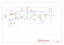
For this little project, I'm using a LM311P. It is has a collector/emitter output. Because my circuit didn't function the way it should, I started debugging.
With the collector unconnected the emitter (pin 1) still sinks (11 mA) and sources (20 mA) current, when applying a square wave input. I measured mean dc amperage to either rail, so the max is higher. I cannot explain this behavior.
Doing the current measurement on the collector (pin 7) with an unconnected emitter I get 14 mA when sinking, and none when sourcing. But not following the input signal.

Any suggestions what could cause this? Thank you in advance! :)
 

Attachments

  • schematic diagram.png
    schematic diagram.png
    48.8 KB · Views: 13
Wrong forum for this and I didn’t check your schematic but a comparator is used when you want it to go rail-to-rail based on a trigger voltage with a small amount of hysteresis. Useful for instance in an over voltage or under voltage detector, zero crossing detector, or a delta-sigma converter. An op amp does similar things in some circuits with its high gain but it’s intended to be very linear and slow where this is not.
 
With the collector unconnected the emitter (pin 1) still sinks (11 mA) and sources (20 mA) current, when applying a square wave input. I measured mean dc amperage to either rail, so the max is higher. I cannot explain this behavior.
Doing the current measurement on the collector (pin 7) with an unconnected emitter I get 14 mA when sinking, and none when sourcing. But not following the input signal.

Any suggestions what could cause this? Thank you in advance! :)
When the emitter is disconnected you may be seeing the current through a forward biased base-collector junction in one direction, but no current when it is reverse biased.

With the collector disconnected you may be seeing some more complex behaviors. If the N-type collector to P-type substrate junction gets forward biased, the SCR formed by the NPN within the substrate may get turned ON.
Also, carriers injected into the substrate by a forward biased collector-substrate junction could cause unwanted behavior in other devices within the IC.

The bottom line is that I don't think disconnecting terminals on the output NPN is a good technique for diagnosis, because the NPN is not isolated but it is integrated on a semiconductor substrate with other devices.

What problems are you observing with the functionality of your circuit? If you make measurements across the circuit lineup where do you start seeing a discrepancy from what you expect?
 
Status
Not open for further replies.
Top