Downsizing Wires

Status
Not open for further replies.
Per job specifications, all homerun conductors have to be #10 or larger. For indoor lighting circuits this was interpeted as only to the first box, due to wording "homerun". The wire was reduced to #12 going to the next boxes.
Is #10 required between every box and only the taps to the fixtures be reduced?
Outside lighting runs are 250 feet to the first box and 50 feet between the next five bollards or 450 feet. Is Voltage drop length figured to the first box or to the end of the run. If to the end of the run is reducing wire size allowed?
 

raider1

Senior Member
Staff member
Location
Logan, Utah
Welcome to the forum.:)

Per job specifications, all homerun conductors have to be #10 or larger. For indoor lighting circuits this was interpeted as only to the first box, due to wording "homerun". The wire was reduced to #12 going to the next boxes.

What size breaker are you using to protect the circuit?

If this is a job spec you will want to get clarification from the designer.

Is Voltage drop length figured to the first box or to the end of the run. If to the end of the run is reducing wire size allowed?

Typically voltage drop would be calculated all the way to the end of the run. You can reduce the size of the conductors toward the end of the run if you want. Also keep in mind that as the loads are dropped off in the run the voltage drop will change.

Chris
 

drbond24

Senior Member
This is a question best left for the designer if you have a way of contacting them.

Any time I designed something similar, my intention was that the homerun was only to the first box. I can't speak for your designer, though.

Voltage drop is calculated over the entire length of the circuit, but as loads branch off and wire sizes change, the caluclation changes. You can't do one voltage drop calc for the entire circuit; you'd have to do it in stages. Your designer should have already done this...:confused:
 

480sparky

Senior Member
Location
Iowegia
.............Voltage drop is calculated over the entire length of the circuit, but as loads branch off and wire sizes change, the caluclation changes. You can't do one voltage drop calc for the entire circuit; you'd have to do it in stages. Your designer should have already done this...:confused:

Yes you can:

voltdropmultiloads.jpg
 

drbond24

Senior Member
Yes you can:

voltdropmultiloads.jpg

Ok...that picture doesn't make any sense at all to me. :)

I will clarify what I meant a little more just in case that will help. I was saying that you can't just run the voltage drop equation one time to get a voltage drop for the whole circuit. You will need to apply that equation on each 'section' of the circuit to get the voltage drop for that section. Then you can add up the sections to get the voltage drop for the part of the circuit you're concerned with.

If that is incorrect, feel free to correct me but you're going to have to do it with something other than that picture. :D Maybe if you drew something on construction paper using crayons it'd be more on my level. :D:D
 
This is a question best left for the designer if you have a way of contacting them.

Any time I designed something similar, my intention was that the homerun was only to the first box. I can't speak for your designer, though.

Voltage drop is calculated over the entire length of the circuit, but as loads branch off and wire sizes change, the caluclation changes. You can't do one voltage drop calc for the entire circuit; you'd have to do it in stages. Your designer should have already done this...:confused:


I agree with this line of thinking, if one is changing the size of the conductors as one gets further away.
I also am curious as to what size is the fusing of the conductors. Remember you may have to be following ther requirements of Article 411.
 

480sparky

Senior Member
Location
Iowegia
Ok...that picture doesn't make any sense at all to me. :)

I will clarify what I meant a little more just in case that will help. I was saying that you can't just run the voltage drop equation one time to get a voltage drop for the whole circuit. You will need to apply that equation on each 'section' of the circuit to get the voltage drop for that section. Then you can add up the sections to get the voltage drop for the part of the circuit you're concerned with.

If that is incorrect, feel free to correct me but you're going to have to do it with something other than that picture. :D Maybe if you drew something on construction paper using crayons it'd be more on my level. :D:D


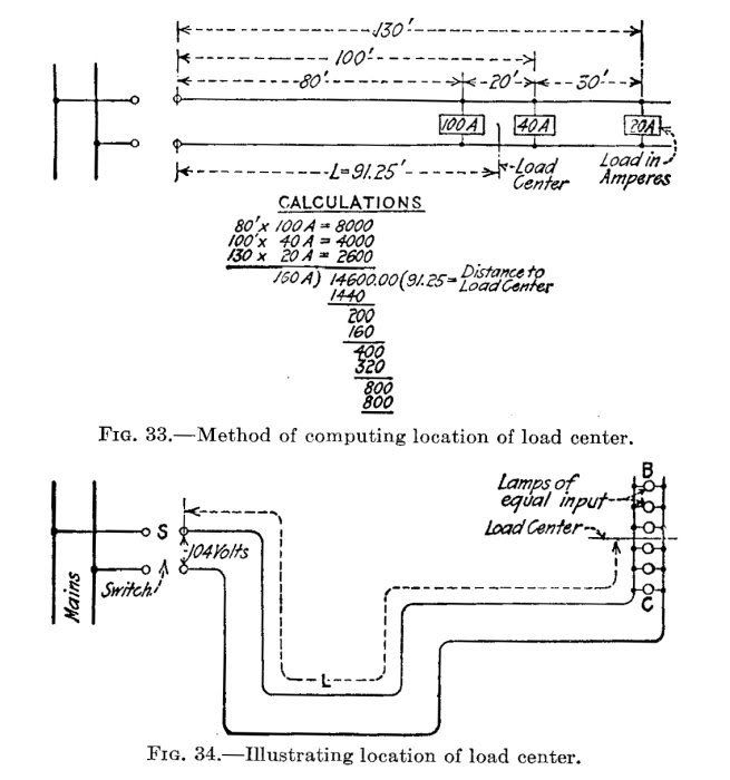
There's two load calculations in the image. The top one shows you how to calculate voltage drop when the loads vary and/or at uneven distances from the source.

In that example, there are 3 loads, 100a, 40a and 20a. The 100a load is 80' from the mains, the 40a at 100' and 20a at 130'. To calculcate VD, it shows how to determine the "load center", or the mathematical 'center' of those loads. In this case, it is 91.25 feet. That is the number you use in your VD calculation.


The lower portion only means that if the loads are evenly spaced and of equal amperage, you use the 'center' of the loads for the 'length' needed for the VD calc.
 

drbond24

Senior Member
There's two load calculations in the image. The top one shows you how to calculate voltage drop when the loads vary and/or at uneven distances from the source.

In that example, there are 3 loads, 100a, 40a and 20a. The 100a load is 80' from the mains, the 40a at 100' and 20a at 130'. To calculcate VD, it shows how to determine the "load center", or the mathematical 'center' of those loads. In this case, it is 91.25 feet. That is the number you use in your VD calculation.


The lower portion only means that if the loads are evenly spaced and of equal amperage, you use the 'center' of the loads for the 'length' needed for the VD calc.

Ok, I understand I think. I don't see how it is very useful, though. That method would get you one number for voltage drop for the entire circuit, but what would it mean? You'd get an average that may not even actually exist...

Maybe its just me. I'll make up an example and work through it both ways and see what happens. If I learn anything, I'll share it. :)
 

480sparky

Senior Member
Location
Iowegia
Ok, I understand I think. I don't see how it is very useful, though. That method would get you one number for voltage drop for the entire circuit, but what would it mean? You'd get an average that may not even actually exist...

Maybe its just me. I'll make up an example and work through it both ways and see what happens. If I learn anything, I'll share it. :)

This method is only if you are going to install one size conductor through the entire circuit.

You certainly could calculate the VD to the first load, then use the lower voltage as a starting point for calculating VD on the remainder of the circuit, and keep working your way down the line. Feed a load, then drop the wire size to the next. Feed the next load, then reduce the wire size again...... continue until you get to the end. Then size your breaker for the smallest wire and/or load. But this would be very tedious and error-prone if you've got lots of loads like lot lighting.

I find the 'load center' method much easier.... calculate one 'length' to enter in to the VD calc, and install one size of pipe and wire.
 

roger3829

Senior Member
Location
Torrington, CT
Per job specifications, all homerun conductors have to be #10 or larger. For indoor lighting circuits this was interpeted as only to the first box, due to wording "homerun". The wire was reduced to #12 going to the next boxes.
Is #10 required between every box and only the taps to the fixtures be reduced?
Outside lighting runs are 250 feet to the first box and 50 feet between the next five bollards or 450 feet. Is Voltage drop length figured to the first box or to the end of the run. If to the end of the run is reducing wire size allowed?
Homerun would be from the panel to the first box in MY opinion. You would have to check with the engineer. to see if that's what HE meant
 

hurk27

Senior Member
Yes you can:

voltdropmultiloads.jpg

This appears to be an old Edison load balance, voltage drop formula , used to keep his Lamps at the same brightness in a long run of lamps, I have used this in landscape lighting ant it works good when lamps are not spread out very far but are on a long run to the lamps. but in long runs of many lamps then I use a ring circuit. but for voltage drop figures in ballasted lights, I would used the afore mention of figuring each section.
 
Status
Not open for further replies.
Top