driven ground rods 6' apart

Status
Not open for further replies.

JDB3

Senior Member
There was a thread some time back describing why driven ground rods should be a min. of 6 feet apart. I can not find this now, any body out there to help me? Thanks. One utility company, is talking of requiring the electrical contractor to install a 3/4" X 8' ground rod for a 320 amp rack service that is within 18" to 24" of their pedestal that they have a ground rod in. We are required to install a #2 ground from the meter socket through a 3" nipple (along with our conductors feeding the meter socket) for them to connect to their ground rod. By the way, they also have us put bonding bushings (with #6 bonding wire) on both ends of the 3" nipple, & connected to a ground bar in the meter socket & they connect it to their ground rod also. Bunches of grounding & bonding. :jawdrop:
 
Just keeping it simple here - the ground rod has voltage "zones" encircling it. 6 feet has been determined the general rule as far as minimum distance you should keep rod away from each other so the stronger portions of the zones do not overlap, and obtaining maximum effectiveness of each rod. Place them too close together and the overlapping zones may make two rods only as effective as one or at least some number between 1 and 2.
 
Just keeping it simple here - the ground rod has voltage "zones" encircling it. 6 feet has been determined the general rule as far as minimum distance you should keep rod away from each other so the stronger portions of the zones do not overlap, and obtaining maximum effectiveness of each rod. Place them too close together and the overlapping zones may make two rods only as effective as one or at least some number between 1 and 2.

What kwired said. Drive the first ground rod, for ten foot ground rods, the second rod should be ten feet from the first.

This is a good rule of thumb.
 
I have heard the further the better and also twice the length of the rods. 8' rod then drive the second one 16' away. Persomally I use the CEE whenever possible.
 
Last edited:
Just keeping it simple here - the ground rod has voltage "zones" encircling it. 6 feet has been determined the general rule as far as minimum distance you should keep rod away from each other so the stronger portions of the zones do not overlap, and obtaining maximum effectiveness of each rod. Place them too close together and the overlapping zones may make two rods only as effective as one or at least some number between 1 and 2.
Yes, I saw a diagram with equipotential 'shells' surrounding each rod. The shell radius was perhaps equal to the ground rod depth.
 
I have heard the further the better and also twice the length of the rods. 8' rod then drive the second one 26' away. Persomally I use the CEE whenever possible.

I'm confused.............. how does twice the length of an 8' Rod add up to 26' ??
 
I've heard all sorts of 'rules of thumb' and other assertions - even seen an FPN or two - yet only my following coment is based on real data.

Very simple: the farther apart electrodes are, the better they work. This relationship is NOT linear. Let's imagine three situations:

In the first, you have a choice between placing the second electrode 1" away or 13" away. HUGE improvement when the second rod is 13" away.

In the second situation, you have a choice of placing the second electrode 6-ft away or 7-ft away. Very little improvement for the 7-ft. placement.

Finally, you have a choice between placing the second electrode 10-ft or 11-ft away. Essentially no advantage to placing it that foot farther apart.

The data I use to support these statements can be found in the American Electricians' Handbook, where they publish a very nice graph of the relationship. It's a lovely hyperbolic curve, with your 'point of diminishing returns' right at the 6-ft. mark. The footnotes tell you where they got the numbers.

There is also a similar graph on the same page about electrode length.
 
the real answer is that it is required by code.

a related question would be why do we need a second rod? the answer to that is also because it says so in the code.
 
the real answer is that it is required by code.

a related question would be why do we need a second rod? the answer to that is also because it says so in the code.

What if I change the question to why does code say we need a second rod?:)

Who determined that one rod was acceptable if you have 25 ohms or less resistance to one rod ? Thus the cost of testing the first

rod makes it econimical to just drive the second rod.

The moral of the condrumun is to use the Ufer ground where practicle.
 
Hey Dennis, what is CEE ? What is the American Electricians Handbook? Don't recall hearing about it.Thanks all. A very merry & Blessed Christmas to one & all !!!
 
What if I change the question to why does code say we need a second rod?:)

I think they are reluctant to remove the requirement because they made people spend a ton of money on a second rod over the years for no good reason. It would be like admitting to a mistake and many people are just unable to do that.
 
I think they are reluctant to remove the requirement because they made people spend a ton of money on a second rod over the years for no good reason. It would be like admitting to a mistake and many people are just unable to do that.
They could claim the reasonable person standard. They acted as a reasonable person would have, knowing what they knew at the time.
 
They could claim the reasonable person standard. They acted as a reasonable person would have, knowing what they knew at the time.

The problem is they did not KNOW anything that would suggest two rods was even a good idea. It was and remains mostly a matter of tradition if nothing else.
 
Yes, I saw a diagram with equalpotential 'shells' surrounding each rod. The shell radius was perhaps equal to the ground rod depth.

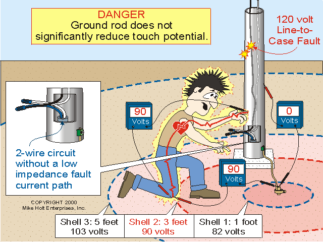
The term shells are just a reference to a point of distance from a rod or other type of electrode in Earth, it is a function of the measured resistance of Earth in the form of R per CM of soil, it is not just in two dimensions but three as this shell follows the rod to its depth and under it keeping the same distance, the shell is just a term used to understand how the resistance of soil works, it is not an area of equalpotential as the resistance will still vary when measured closer or farther from the rod, to the point of max "sphere of influence" 26 feet in most common soil.

The 3' reference is the most common used as it is a point that a person who could be in contact with a live rod (120 volts) or light standard that is only grounded by a rod, and if kneeling will have 75% of voltage or 90 volts between his knee and the electrified light pole pole.

The true term is the "sphere of influence" which is a point from the rod out to a distance of about 26 feet, beyond this point the rod no longer has very little to any influence on the Earth this depends upon the resistivity of the soil r per cm, the lower the resistance of the soil the smaller the SOI, it also affect the 75% voltage drop stated above and now instead of a 3 foot shell it can be a 2'6" shell that will have a 75% voltage drop.

As stated the best separation of ground rods is 2 times the length of the rod, but the NEC minimum is 6 feet once you get beyond the SOI of the rod it makes no difference in the measured resistance as the reading will stay the same.

Here is an old thread where a member did some point measurements to understand how an electrode connection to Earth works:

"Earth Shells Experiment = time to eat crow!"

It will help you understand how little a ground rod contributes to safety of an electrical system, but it is hard to convince old school electricians, and utility workers and engineers as they play with much higher voltages and it seems to function for them.

And with the above said, this thread is another example of a utility requirement by someone who does not have the knowledge of how Earth electrodes even work and what they can or cannot do.

Here is also a graphic from MH that also give a little visual aid to what I was talking about:
touch.gif
 
Last edited:
Who determined that one rod was acceptable if you have 25 ohms or less resistance to one rod ? Thus the cost of testing the first

rod makes it econimical to just drive the second rod.

The moral of the condrumun is to use the Ufer ground where practicle.

I think they are reluctant to remove the requirement because they made people spend a ton of money on a second rod over the years for no good reason. It would be like admitting to a mistake and many people are just unable to do that.

Until they changed the wording in 2008 or 2011 (I forget which year it was changed) you did not have to drive two rods unless you determined the first was more than 25 ohms. Now you must verify the first is less than 25 ohms or drive the second rod. Before you found most installations only had one rod, and nobody even knew what the resistance was because they had no way or knowledge or just did not want to check the first one. Now you have to use two rods unless you actually do check the first one and it ends up being less than 25 ohms.

Hey Dennis, what is CEE ? What is the American Electricians Handbook? Don't recall hearing about it.Thanks all. A very merry & Blessed Christmas to one & all !!!

CEE is "concrete encased electrode" some all call it "Ufer", which is the name of the guy that came up with this concept.

American Electricians Handbook is a good book to have. I have one that is about 25 years old, still open it up at times. It was on our books list when I was in school, but was about the only one on the list that did not specifically go with a particular class. NEC was also not specific to a particular class, but naturally was required for the actual class on the "NEC".
 
Status
Not open for further replies.
Top