E-Stop in motor controls

Status
Not open for further replies.

W.I.T. Engineering

New member
Location
Colorado

What does the NFPA say about the use of the E-Stop circuit when it comes to breaking the power to a three phase motor? If we have a motor controller that has dynamic breaking, does the code allow the E-stop circuit to apply dynamic braking and then interrupt the power to the motor with a contactor? Is the contactor interrupt before or after the motor controller? Does the E-stop circuit require a contactor interrupt to the motor or is the motor controller sufficient?
 
NFPA 79 is a good start

NFPA 79 is a good start

NFPA 79

Stop Categories:

Category 0 = an uncontrolled stop by immediately removing power to the machine actuators

Category 1 = a controlled stop with power to the machine actuators available to achieve the stop then remove power when the stop is achieved.

Category 2 = a controlled stop with power left available to the machine actuators.

Each machine shall be equipped with a Category 0 Stop.

Category 0,1, and/or 2 stops shall be provided where indicated by an analysis of the risk assessment and the functional requirements of the machine.

The emergency stop shall function as either a Category 0 or a Category 1 Stop. The choice of the category of the emergency stop shall be determined by the risk assessment of the machine.

10.7.5 Local Operation of the supply Disconnecting Means to Effect Emergency Stop.

10.7.5.1 The supply disconnecting means shall be permitted to be locally operated to serve the function of emergency stop as follows:
(1) Where it is readily accessible to the operator
(2) Where it is of the type described in 5.3.2(1), 5.3.2(2), or 5.3.2(3)

5.3.2
(1) A listed motor circuit switch (switch disconnector) rated in horsepower.
(2) A listed, branch circuit rated molded case circuit breaker
(3) A listed molded case switch.
 
NFPA 79 one more note

NFPA 79 one more note

9.2.5.4.2.2. Emergency switching off shall be accomplished by disconnecting the incoming supply circuit of the machine effecting a Category 0 Stop. Where the machine cannot tolerate the Category 0 stop, it shall be necessary to provide other protection (e.g., against direct contact), so that emergency switching off is not necessary.
 

jim dungar

Moderator
Staff member
Location
Wisconsin
Occupation
PE (Retired) - Power Systems
The NEC (NFPA70) does not address the specifics of an E-Stop operation.

However, NFPA79 (Electrical Standard for Industrial Machinery) does. In most jurisdictions NFPA79 is not mandatory.
 
OSHA and the "General Duty Clause"

OSHA and the "General Duty Clause"

What about OSHA's General Duty Clause?

SEC. 5. Duties
(a) Each employer --


(1) shall furnish to each of his employees employment and a place of employment which are free from recognized hazards that are causing or are likely to cause death or serious physical harm to his employees;

(2) shall comply with occupational safety and health standards promulgated under this Act.

29 USC 654
(b) Each employee shall comply with occupational safety and health standards and all rules, regulations, and orders issued pursuant to this Act which are applicable to his own actions and conduct.

Carl Van Tilburg
Electrical Engineer, PE
 

jim dungar

Moderator
Staff member
Location
Wisconsin
Occupation
PE (Retired) - Power Systems
The Category 0 stop in NFPA79 9.2.5.3.1 corresponds with all of the different NEC requirements for a loadbreak "disconnecting means".

However NFPA79 9.2.5.3.2 does not require that a Category 0 stop be the only method by which a piece of equipment can be E-stopped.

So, while OHSA could cite NFPA79 as a promulgated standard, there is nothing in NFPA79 that limits which E-stop functions may be used.
 

iwire

Moderator
Staff member
Location
Massachusetts
Jim am I understanding this correctly?

The NEC required disconnecting means fulfills NFPA 79s Each machine shall be equipped with a Category 0 Stop.

And now that we have a category 0 stop all the other E-stops could be Category 1?

It happens that in the last month I have been involved adding safety switches on equipment. The way these are set up if you where to open a guard the motor will be shut down but dynamic braking comes on.
 

jim dungar

Moderator
Staff member
Location
Wisconsin
Occupation
PE (Retired) - Power Systems
iwire said:
Jim am I understanding this correctly?

The NEC required disconnecting means fulfills NFPA 79s Each machine shall be equipped with a Category 0 Stop.

And now that we have a category 0 stop all the other E-stops could be Category 1?

It happens that in the last month I have been involved adding safety switches on equipment. The way these are set up if you where to open a guard the motor will be shut down but dynamic braking comes on.

A little clarification: While NFPA79 Chapter 9 is for control circuits, 9.2.5.4.2.2 allows a power circuit disconnect instead. An NEC disconnect (i.e. 670.4(B)) must also remove all other machine power also (ie. hydraulics, steam, and air). So if the machine is not "self-contained" an NEC disconnect only may not be suffcient.

A risk analysis (9.2.5.4.1.4) must be performed when deciding on which type of E-stop control circuit to use.
 

iwire

Moderator
Staff member
Location
Massachusetts
Thanks Jim.

jim dungar said:
A risk analysis (9.2.5.4.1.4) must be performed when deciding on which type of E-stop control circuit to use.

I am sure this factory has done what is required, I am just helping with the installation. :)

It seems their risk assessment is that absolutely everything is a risk, they buy brand new equipment and add all kinds of guards all with dual channel safety switches going back to a safety relay.

It's been interesting and fun doing something different. :cool:
 
Ansi

Ansi

Also, watch "Incorporation by Reference" of OSHA.

ANSI has many standards referenced to by OSHA.

Actually, the first standard for the safe use of machinery was ANSI B11.1-1926.

ANSI B11 standards cover applications at the machine level.

UL produces standards for specific safety items or devices.

e.g.

ANSI B11.19 "Performance Criteria for Safeguarding". This is where the redundancy comes from in the safety circuits. The probability of two or more failing is less than one failing (i.e. single point of failure).

Carl Van Tilburg
Electrical Engineer, PE
 

realolman

Senior Member
iwire said:
....It seems their risk assessment is that absolutely everything is a risk, they buy brand new equipment and add all kinds of guards all with dual channel safety switches going back to a safety relay.....
. :cool:

I don't like those dual channel things. What is their purpose? I can't see how two parallel series circuits in one switch is better or safer than one series circuit?
 

iwire

Moderator
Staff member
Location
Massachusetts
realolman said:
I can't see how two parallel series circuits in one switch is better or safer than one series circuit?

Right off the bat it occurs to me that the chances of two contacts sticking closed at the same time in the same switch is half of the chance of one contact sticking closed.

But I only just started working with these. As I understand it the safety relay also times the time between each circuit breaking. If they do not break at close to the same time the safety relay opens. It seems this could catch a contact that was starting to hang up.

That said this place uses these dual channel gizmo's for everything.

It will not surprise me if they have me put two 'finger buttons' with dual channel safety controls on the water fountain in the hall way. :roll:

Than again, the work is warm, dry and interesting.....I will add safety switches to whatever they want. :)
 
What???

What???

The contacts in the safety relay are in series NOT parallel.

Consult the literature that came with the relay. There are wiring diagrams that will make the concept very clear.

Carl Van Tilburg
Electrical Engineer, PE.
 

jim dungar

Moderator
Staff member
Location
Wisconsin
Occupation
PE (Retired) - Power Systems
I have seen stop circuits with a combination of two contacts in parallel (verifies both buttons have been released) to one input of safety relay and series (verifies at least one button has been operated) to a different input.
 

realolman

Senior Member
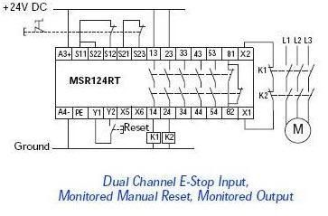
I'd like to take this opportunity to air a gripe... This is the drawing you get with the "safety relay" that monitors the "dual channel" safety circuit previously mentioned. Do you see the dual channel switch? Are the channels in series or parallel? Heck if I know. Looks parallel to me, but I guess that depends on what's in the "black box". What is the "concept" here?

safetyrelay-1.jpg


Here, I think, are some better questions...What kind of a crappy schematic is this? ... Why don't I get one that is informative, and in English? ( I got this from the internet... the one in the box had three languages... none English ) How do I troubleshoot this thing, when I don't know what it's doing? What is going on in this "safety relay" that makes it superior to a "regular" relay.... besides, I'm sure, a hefty price tag. Are you trying to make it difficult?

this seems to be the kind of stuff you get all the time these days...overblown black boxes... .:mad:
 
Last edited:

iwire

Moderator
Staff member
Location
Massachusetts
realolman said:
Do you see the dual channel switch?

safetyrelay-1.jpg

Yes, the contacts connected to S11 S12 and S21 S23 are part os a dual Chanel switch. The dotted line shows they are connected.

That said the directions do stink.
 

jim dungar

Moderator
Staff member
Location
Wisconsin
Occupation
PE (Retired) - Power Systems
I have had ggod luck with reading about the different safety relay offerings from Telemecanique, STI/Gaurdmaster, and Pilz. These are very common in Europe so finding American language instructions is not common.

http://ecatalog.squared.com/techlib/docdetail.cfm?oid=0900892680169d88 starting on page 152, and page 166 has an equivalent device as in the OP. There is a "timing diagram" and an internal connection showing all of the series and parallel circuits.
 

petersonra

Senior Member
Location
Northern illinois
Occupation
engineer
Looks like a normal safety relay to me. You get used to them after a while, just like anything else.

The idea is to have two seperate sets of contacts monitored seperately to make sure that if you have a single failure, it not only does not compromise function, but is detected and you are forced to fix it.

There is not much inside the safety relay you can diagnose. It either works or it does not work.

By the way, the motor contactors K1 and K2 have to have force guided contacts. Regular NEMA starters are not allowed in this configuration.


realolman said:
I'd like to take this opportunity to air a gripe... This is the drawing you get with the "safety relay" that monitors the "dual channel" safety circuit previously mentioned. Do you see the dual channel switch? Are the channels in series or parallel? Heck if I know. Looks parallel to me, but I guess that depends on what's in the "black box". What is the "concept" here?

safetyrelay-1.jpg


Here, I think, are some better questions...What kind of a crappy schematic is this? ... Why don't I get one that is informative, and in English? ( I got this from the internet... the one in the box had three languages... none English ) How do I troubleshoot this thing, when I don't know what it's doing? What is going on in this "safety relay" that makes it superior to a "regular" relay.... besides, I'm sure, a hefty price tag. Are you trying to make it difficult?

this seems to be the kind of stuff you get all the time these days...overblown black boxes... .:mad:
 
Last edited:

winnie

Senior Member
Location
Springfield, MA, USA
Occupation
Electric motor research
iwire said:
Right off the bat it occurs to me that the chances of two contacts sticking closed at the same time in the same switch is half of the chance of one contact sticking closed.

Well, _presuming_ that contact sticking is a random failure, and that failure of either contact set is an independent event, the chance of _both_ contacts sticking is the _square_ of the change that either contact will stick.

However it is not clear that these are two independent events; both contacts will age at the same rate, and are powered by the same system, and are in pretty much the same environment.

Still I'd expect a substantial improvement in reliability by using a dual contact arrangement.

-Jon
 
Status
Not open for further replies.
Top