e-stop question

Status
Not open for further replies.
s it acceptable to wire e-stop buttons in series in other words take 2 e-stop buttons and wire them in series to a single channel e-stop relay.

Thanks
 

jim dungar

Moderator
Staff member
Location
Wisconsin
Occupation
PE (Retired) - Power Systems
Be careful of the wiring of E-stop buttons into a safety relay. Some relays have 'checking' circuits which use two sets of contacts on your stop button, others don't.
 

drbond24

Senior Member
s it acceptable to wire e-stop buttons in series in other words take 2 e-stop buttons and wire them in series to a single channel e-stop relay.

Now that this has been successfully asked and answered, I'm going to invade with a sidebar question.

Is there any other way to wire e-stops but in series? I've never done this or been involved with it, I'm just trying to work it out in my head. The machines I worked with at my last place of employement had over a dozen e-stops located all over the machine. Any one of them needed to shut the whole thing down. If they weren't all wired in series, how else would that get accomplished? A separate circuit for each button?
 

Jraef

Moderator, OTD
Staff member
Location
San Francisco Bay Area, CA, USA
Occupation
Electrical Engineer
Now that this has been successfully asked and answered, I'm going to invade with a sidebar question.

Is there any other way to wire e-stops but in series? I've never done this or been involved with it, I'm just trying to work it out in my head. The machines I worked with at my last place of employement had over a dozen e-stops located all over the machine. Any one of them needed to shut the whole thing down. If they weren't all wired in series, how else would that get accomplished? A separate circuit for each button?
Some Safety Relays will allow you to wire them in parallel, (or a "cascade"); it's done when it's important to know WHICH e-stop was pushed. An example would be as follows:

A machine with 3 e-stops, A, B and C plus 3 machine zones, 1, 2 and 3. If you hit A, it stops zones 1-3, but if you hit B, it only stops 2 and 3, and C only stops 3. The reason is, stopping the entire machine presents a greater danger than stopping only the zone where an immediate danger is present.
 

drbond24

Senior Member
Some Safety Relays will allow you to wire them in parallel, (or a "cascade"); it's done when it's important to know WHICH e-stop was pushed. An example would be as follows:

A machine with 3 e-stops, A, B and C plus 3 machine zones, 1, 2 and 3. If you hit A, it stops zones 1-3, but if you hit B, it only stops 2 and 3, and C only stops 3. The reason is, stopping the entire machine presents a greater danger than stopping only the zone where an immediate danger is present.

Ok that makes sense. I just haven't seen anything like that. I worked in a wire manufacturing plant, so the entire machine was threaded up with whatever piece of wire it was running. There wasn't any such thing as stopping just part of the machine.

Thanks for the reply.
 

ohmhead

Senior Member
Location
ORLANDO FLA
Fat bones & grease plant

Fat bones & grease plant

Well we did a new plant in florida and on the start machine to the finish machine line each motor starter in the main motor control center had a aux contact which was wired to the next motor starter aux contact in line series circuit start to finish. All safety /shut down buttons were paralled say 4 per machine and if one machine went down then motors before this point stopped the motors after this point ran . This was to keep the process going and just isolate the problem on line . And four master stops that would shut down the whole plant if need be all motors . These buttons were paralleled to that first motor aux !! just thought you might like to here of a different way .best to ya
 

drbond24

Senior Member
Thanks for the additional information.

I was just thinking about it and I guess the power plant I work at is really the same way except everything is monitored electronically by the computer. If there is a problem, the last thing you want to happen is for the whole unit to trip. The faulty machine or process needs isolated so it can be fixed while the rest of the unit remains running. There is a wall covered in emergency stop buttons for various pieces of machinery, but I've never seen anyone use them (probably why I didn't think of this before).

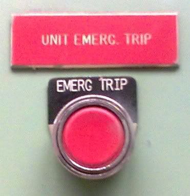
Then, there is the king of all buttons:

Image002.jpg


This one gets a wide berth. Wouldn't want to accidentally lean into it. :D Most of the other e-stops have some sort of cover so it can't accidentally be pressed, but this one doesn't. I figure that if you need this button, you REALLY need it and you don't want the plastic cover in your way to slow you down. Just my guess though.
 

turkish

Member
Location
minnesota
Illuminated E-stop side bar

Illuminated E-stop side bar

As a sidebar to this post, I am wondering where illuminated e-stop requirements are found...

I am trying to figure out if they now need to be lit under normal operation and off when and e-stop condition is present, or is it the other way around?

In our plant we have both examples, and I am trying to look for the regulation on this.
 

drbond24

Senior Member
As a sidebar to this post, I am wondering where illuminated e-stop requirements are found...

I am trying to figure out if they now need to be lit under normal operation and off when and e-stop condition is present, or is it the other way around?

In our plant we have both examples, and I am trying to look for the regulation on this.

You're too late. I've already side-barred this thread! :D

I am not aware of any regulations on this (that by no means says they don't exist, though) but the ones I've seen before were illuminated in the 'off' position.
 

pfalcon

Senior Member
Location
Indiana
There is no restriction on the number of separate Estop circuits present in a machine tool. The restriction is that they must operate to stop the hazard appropriately.

NFPA79:2007 10.3
Red illumination is restricted to the danger, emergency, or fault. Therefore after the Estoop is pressed in an emergency, not before.
 

fmtjfw

Senior Member
wiring series and parallel E Stops

wiring series and parallel E Stops

E Stop buttons Normally Closed contacts are usually wired in series if breaking the loop causes an emergency stop. For this application the buttons do not have a spring return, they stay pushed until manually reset (by pulling out or turning and pulling out). The Normally Open contacts on each button can feed an indicator from a common power source to indicate which button(s) was pushed.

We use this circuit when we have an E Stop contactor that is maintained closed by being powered through the E Stop buttons in series.

E Stop Buttons Normally Open contacts are wired in parallel when they feed a Breaker Shunt Trip coil. They may be momentary contact. If they do not have a spring return a second pair of Normally Open contacts can be used as above.

We use this circuit when a shunt trip breaker is used for E Stop.

/s/ Jim WIlliams
 
Status
Not open for further replies.
Top