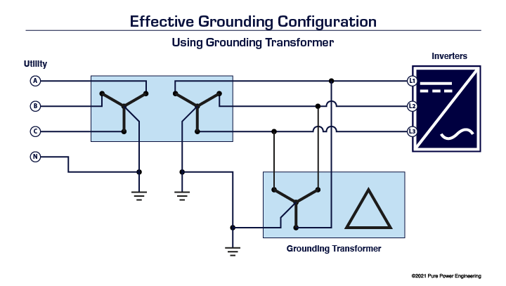
Effective Grounding

Status
Not open for further replies.

SteveO NE

Member
Location
Northeast
Occupation
Engineer
Hi, so without getting into the effective grounding discussion in general as it pertains to PV and rolling our eyes, I have a scenario that is a bit different than usual for me and need some thoughts.

This is a customer with substantial load and an existing 3ph, 480v, 4W Yg-Yg 1MVA service and the PV is behind the meter. Normally I am only designing to accommodate the PV direct to grid when the utility requires a grounding bank and would do a zig zag sized relatively small and part of a SEL relay, shunt trip setup, so I can trip well prior to anything that would exceed thermal ratings of transformer. Theoretically the PV is a perfect balanced load so there isn't much neutral current being shunted to ground so a transient over voltage (TOV) shunt to ground would be pretty obvious and with no rotating mass would fizzle out pretty quick when removing source energy to the inverters that have marginal contributory fault current. With customer load in the mix though, that changes that picture with relatively unknown loads ( I would like to avoid doing a load study).

Normally I just design this inline with a delta service with the service ground through the zig zag. I'm not sure how to manage this with customer load and a Y service. Should I isolate the PV with a Y-D transformer then create a new solid ground through the zig zag? Unfortunately I don't thing a new Y-Yg transformer with monitored Ng current would make the EDC happy. Is it plausible to just tap just the phase conductors on the PV feeder and shunt TOV to ground in parallel to the existing 4 wire system - in my head this would only work if I set my trip setting to the appropriate ratio based on service transformer impedance and zig zag impedance (or if I measure both and sum), but does that really isolate the utility from the TOV? The secondary concern which I would agree as well would be islanding but I think that could be managed with appropriate impedance and x/r of the zigzag.

Sorry possibly rambling a little bit and maybe I am overthinking this but its caused a mind block well trying to design this. I'll go get another cup of coffee and see if it clears up or see if someone here has some insight.

Thanks!

Steve
 
Hmm...no response, are we all shooting in the dark here?

I did have some more thoughts after my cup of coffee, I suppose a reactor is one, but would that be off of the PV feeder or off of the main building service ? Possibly the a solution is a delta to ungrounded wye transformer (delta on the customer load side - Y on the solar side) with a reactor on the neutral and then a bonded neutral.

Maybe I could ask a more pointed and less rambly question on the grounding bank, it seems people do put a grounding bank on wye systems as well, could I do the same as above, pull delta from the interconnection tie breaker, go through zigzag, then use the resultant neutral for the inverter? Its not really a secondary system but because we are avoiding the already grounded current carrier (existing neutral) connection we'd essentially have an ungrounded delta which is what would be needed.
 
I have designed many systems that connect 480/277V inverters to 208/120V services. I use an appropriately sized transformer with a delta primary (utility side) and a wye secondary (inverter side). I bond ground to neutral on the secondary and tie the ground back to the service ground. I do not run a grounding conductor directly from the service to the transformer.
 
Last edited:
The problem is I think some of this "effective grounding" stuff is half voodoo - no one seems to understand it. So it would be nice to just do what the POCO wants and be done with it, however usually they are vague and don't design the "effective grounding system" for you. IIRC one of my POCOs , in their spec book, says something like "there shall be effective grounding, such as a zig zag transformer". So long story short, I'm not sure how I would connect a zig zag to a grounded wye service.
 
... This is a customer with substantial load and an existing 3ph, 480v, 4W Yg-Yg 1MVA service and the PV is behind the meter. Normally I am only designing to accommodate the PV direct to grid when the utility requires a grounding bank and would do a zig zag sized relatively small and part of a SEL relay, shunt trip setup, so I can trip well prior to anything that would exceed thermal ratings of transformer. Theoretically the PV is a perfect balanced load so there isn't much neutral current being shunted to ground so a transient over voltage (TOV) shunt to ground would be pretty obvious and with no rotating mass would fizzle out pretty quick when removing source energy to the inverters that have marginal contributory fault current. With customer load in the mix though, that changes that picture with relatively unknown loads ( I would like to avoid doing a load study).

Something to keep in mind is whether the system as-is would be considered "effectively grounded" by the POCO. If it is effectively grounded, then I don't see that the PV installation would need to provide a lower zero sequence impedance than that appropriate for the PV system's kVA rating alone. In other words, the zero sequence impedance should already be low enough to prevent excessive voltages due to any fault currents coming from rotating motors, etc.

Pg. 7 of the following document shows an example with 480V supplied from a Yg-Yg transformer, and finding the appropriate zero sequence reactance needed from a grounding transformer ( in this case a Yg-Δ ). Of course, you could add a reactor in the neutral if the impedance of available transformers with a high enough current rating is lower than the target value.

https://www.xcelenergy.com/staticfi...cing-Requirements-and-Sample-Calculations.pdf
 
I have designed many systems that connect 480/277V inverters to 208/120V services. I use an appropriately sized transformer with a delta primary (utility side) and a wye secondary (inverter side). I bond ground to neutral on the secondary and tie the ground back to the service ground. I do not run a grounding conductor directly from the service to the transformer.

This is 480V wye service and 480V wye inverters which leads to the comment from synchro but I could theoretically do the same anyway with a 480 delta (utility side) to 480v wye (inverter side) transformer and do the same. I'm not sure I follow what you are saying with grounding...I read that you do and don't tie the transformer to the utility service ground.
Something to keep in mind is whether the system as-is would be considered "effectively grounded" by the POCO. If it is effectively grounded, then I don't see that the PV installation would need to provide a lower zero sequence impedance than that appropriate for the PV system's kVA rating alone. In other words, the zero sequence impedance should already be low enough to prevent excessive voltages due to any fault currents coming from rotating motors, etc.

Pg. 7 of the following document shows an example with 480V supplied from a Yg-Yg transformer, and finding the appropriate zero sequence reactance needed from a grounding transformer ( in this case a Yg-Δ ). Of course, you could add a reactor in the neutral if the impedance of available transformers with a high enough current rating is lower than the target value.

https://www.xcelenergy.com/staticfi...cing-Requirements-and-Sample-Calculations.pdf
Yeah that's the thing. Generally everything here is Yg-Yg and as electrofelon pointed out the utilities just say add effective grounding with no basis or design criteria. I could attempt to do calculations to show that the service transformer is an effective ground; however, they will usually respond with we asked you to add effective grounding because we don't want the service transformer to be the effective ground. They give no guidance from there so its just throwing money at a problem nobody can prove exists.

This latter point is why I would lean towards either what I suggested a delta to ungrounded wye plus reactor or as I believe ggunn is suggesting which is skip the reactor and just do a delta to Yg and call it a day. I should note that I have a redundant utility relay also required so I can monitor and shunt-trip (and/or soft-trip, i.e. set inverter production to zero and avoid a truck roll on a breaker trip) on Ng currents which I might think that in and of itself should be effective grounding.

My preference is to avoid putting anything off of the service transformer because I really do not know or care to do a load study of the customer loads behind the meter in order to prove effective grounding.
 
This is 480V wye service and 480V wye inverters which leads to the comment from synchro but I could theoretically do the same anyway with a 480 delta (utility side) to 480v wye (inverter side) transformer and do the same. I'm not sure I follow what you are saying with grounding...I read that you do and don't tie the transformer to the utility service ground.
The reason we do what we do is because there aren't any large 208/120V inverters, so we use 480/277V inverters and step the voltage down to interconnect with 208/120V services. If we need to connect to a 480/277V service, we don't use a transformer.

The secondaries of our transformers are separately derived, so we don't run an equipment grounding conductor from a service to the transformer. We bond the neutral to ground on the wye side and tie it back to building ground.
 
Last edited:
Can someone point me to an explanation of the need for an "effective ground" that includes a circuit diagram of a fault situation that has negative consequences without the effective ground, along with an illustration of how the effective ground changes the fault behavior?

Thanks
Wayne
 
Can someone point me to an explanation of the need for an "effective ground" that includes a circuit diagram of a fault situation that has negative consequences without the effective ground, along with an illustration of how the effective ground changes the fault behavior?

Thanks
Wayne

Solectria has a go at the theory but still don't really agree with it being a problem for something without rotating mass that contributes nearly nothing to fault current.


The reason we do what we do is because there aren't any large 208/120V inverters, so we use 480/277V inverters and step the voltage down to interconnect with 208/120V services. If we need to connect to a 480/277V service, we don't use a transformer.

The secondaries of our transformers are separately derived, so we don't run an equipment grounding conductor from a service to the transformer. We bond the neutral to ground on the wye side and tie it back to building ground.

The second part is what I don't understand I may need a sketch - I am reading that you do not bring an EGC with the primary conductors but that you tie back the neutral bond on the secondary side to the building GEC. Are you saying there is no EGC in the conduit between the service and the PV transformer (because you then say you tie it back to building)? We do the same in many cases for the same reason most of our runs are in EMT so we require an EGC on the service conductor going to the transformer, then it lands on the chassis of the transformer. Being a separately derived system it also gets its own GEC and EGC on the secondary/PV side that have nothing to do with the building ground. If the transformer is outside then the bond takes place in the transformer itself, if inside then it take place in the first disconnecting means. I would argue this is effective grounding. In this particular case though this customer is has a 480/277 service so there is no transformer actually in the design submitted to the utility and aside from appeasing them I wouldn't put any transformer in at all.
 
Solectria has a go at the theory but still don't really agree with it being a problem for something without rotating mass that contributes nearly nothing to fault current.
Right, so I'm trying to understand what exactly the issue is. Is providing a grounding bank something that is required of all large services? Or is it something that POCOs usually require for any generator attached to their grid? And in the latter case, is it something that only makes sense for generators with rotating mass (large potential energies in the inertia thereof)? But POCOs are applying it to PV generators either out of ignorance or as an intentional regulatory obstacle for PV?

Because the Solectria white paper states:

"Solectria tested commercial and utility scale inverters by subjecting them to different types of faults. The worst case fault current obtained from these tests is limited to less than 120% of the inverter’s rated current and the inverter shuts off within 2 cycles. The fault current from the inverter flows to the grid side mostly not to the grounding bank as the grounding bank impedance is much higher than the feeder line impedance. For this reason, the fault current contribution from an inverter will be ignored in the grounding bank current rating."

So if the idea is that "generators that can contribute fault currents to faults on the grid need to assist with effective grounding" (not really sure what that is, yet), it sounds like it shouldn't apply to PV inverters.

I guess I should have clarified that my earlier question was about what "effective grounding" is in general, and was not PV specific.

Cheers, Wayne
 
Right, so I'm trying to understand what exactly the issue is. Is providing a grounding bank something that is required of all large services? Or is it something that POCOs usually require for any generator attached to their grid? And in the latter case, is it something that only makes sense for generators with rotating mass (large potential energies in the inertia thereof)? But POCOs are applying it to PV generators either out of ignorance or as an intentional regulatory obstacle for PV?
...
While I know less than anyone else on this thread, I think I know enough to opine that you are on the right track here.
 
Besides the apparent theoretical issues of what it accomplishes and when it is necessary, I have always found it rather bizarre how utilities are so vague on the requirements for effective grounding. It seems like for pretty much everything else, utilities are very specific about what they want.
 
... the Solectria white paper states:

"Solectria tested commercial and utility scale inverters by subjecting them to different types of faults. The worst case fault current obtained from these tests is limited to less than 120% of the inverter’s rated current and the inverter shuts off within 2 cycles. The fault current from the inverter flows to the grid side mostly not to the grounding bank as the grounding bank impedance is much higher than the feeder line impedance. For this reason, the fault current contribution from an inverter will be ignored in the grounding bank current rating."
I interpret that particular paragraph as saying that inverters will contribute a relatively small amount of ground fault current compared to what the grid can provide, and so when sizing grounding transformers the inverters can be ignored.

I think there may be a concern that if a ground fault on a local POCO distribution line opens an upstream protection device, then the impedance looking into the grid could increase significantly. An so even if the output current from inverters only persists for a few cycles there might be a short duration L-N overvoltage that could possibly damage some loads, etc. if the total load current is less than what the inverter is providing. A grounding transformer could reduce that possibility.
 
FWIW from here:


Effective Grounding During Ground Fault Events. When substation equipment isolates a faulted line in the grid, it coincidently isolates the system ground reference for that grid section. During the brief moment it takes the PV DER to detect its islanded condition and disconnect, it will continue to power loads. If not equipped with appropriate effective grounding, it may also produce a potentially damaging temporary overvoltage (TOV) on the unfaulted lines

I'm not following this. Maybe someone else does and can explain to me why it isn't hogwash.
 
It's simple, really. Grounding is voodoo. AHJs have differing opinions as to what is correct; we find out what the AHJ wants, and we design and build accordingly. Ours is not to reason why; ours is to do as the AHJ directs or fail the inspection.
 
We put the grounding transformer on the supply side or load side of the PV transformer, it really depends on what the utility wants. If the grounding transformer is on the load side then the PV transformer has to be Ygyg to be transparent to zero-sequence ground fault current. If the grounding transformer is on the supply side then the PV transformer can have any winding configuration you want.
If you have a 3 wire delta service then there is no need for effective grounding, since there is no line to neutral over voltage possible.
 
Status
Not open for further replies.
Top