Electromagnetic pollution (stray voltage)

Status
Not open for further replies.

KurtWG

Member
I've been writing about this topic for several years and am concerned primarily with the effects of all forms of electromagnetic pollution on human health. One factor of particular concern is the accurate measurement of these phenomena.

Does anyone have suggestions for a systematic protocol that could be used to take these measurements, i.e., instruments, techniques, procedures?

I'm hoping the instrumentation could be affordable by a qualified electrician or contractor. Some might be accessible to laypeople. The phenomena of interest include ground currents, EMF and "stray voltage."

Or is the electromagnetic environment/protocol so complex that it's not possible to approach systematically?

Perhaps there are already references on this topic. I apologize in advance if this is off-topic for this forum.

Thanks.
 

karl riley

Senior Member
The best all-purpose meter (I use it) is the Bell 4080. You could send me a private message for more info, but you need to ask more specific questions.

Karl Riley
 

robbietan

Senior Member
Location
Antipolo City
EMF levels can be read with ease using the Bell 4080. However, emf levels vary constantly, specially the fields from transmission lines. As the load of the transmission line varies during the day and varies for every season, you will really have to log entries to get the whole picture
 

ghostbuster

Senior Member
Please be also aware magnetic fields exist on all 3 axis(x,y,z).The cheaper handheld meters generally only measure the field on 1 axis.You would need to rotate this style of meter on all 3 axis until the peak level was found.:)
 
Hi Kurt,

I see that you have been invovled with stray voltage for several years and I may be just beginning a venture into educating myself on the subject. I run a small dairy farm in southern WI and there is an electrical substation proposed to be in operation by December 2007 which is about 1000 ft from my barn. Everything I've found so far on the Internet and talking with those who have experienced anything of this fashion have been negative. I'm looking for positive situations between livestock and power. Unfortunately, I don't much understand the first thing about a substation that steps down power from 69000 volts to 7200 for distribution. Any help would be most appreciated. Thanks in advance.
 

karl riley

Senior Member
About instrumentation. Ghostbuster, your were misinformed. A simple single axis gaussmeter is used best by rotating it until you get the highest reading. This is the correct reading, the same as you would get with a 3-axis gaussmeter. You are reading the resultant of the various phases. It is actually a little more accurate than the 3-axis since you get a simultaneous reading as opposed to the time delay in the three-axis internal calculation.

Now you can hold and record the partial readings in each of the three-axis positions, but this would be an even greater time delay than in the 3-axis meter. And very cumbersome. I know this has been a published method, but it is due to ignorance, if I may be blunt. (Old guys get blunt).

As to recording, the cheapest way is to get a single-axis sensor and plug it into a recording voltmeter (multimeter) at the millvolt level. 1 mV = 1 mG. These are av ailable at magneticsciences.com. Called the Magcheck 95, it reads correctly for 50 Hz up to about 3kHz. I and the present owner of MSI developed this sensor. It plugs into the standard multimeter jacks. I get no remuneration from these sales.

Karl
 

ghostbuster

Senior Member
karl riley said:
About instrumentation. Ghostbuster, your were misinformed. A simple single axis gaussmeter is used best by rotating it until you get the highest reading. This is the correct reading, the same as you would get with a 3-axis gaussmeter. You are reading the resultant of the various phases. It is actually a little more accurate than the 3-axis since you get a simultaneous reading as opposed to the time delay in the three-axis internal calculation.

Karl

I agree 100% with you in principle only."Generally" the cheap single axis units sold are enclosed in a simple box.This box has the probe and the digital display combined.I have seen many of my clients hold this box directly in front of them to be able to read the display.As you know,this will not give them the correct reading.It could be wrong by 1 to 10 times++.To use a single axis unit correctly,the probe must be free to rotate separately from the display unit.

I own a single axis independent probe coupled with a HP spectrum analyzer and it is great for finding and confirming the true source of each magnetic field within a building.I also own a DC probe used for similar type of investigations.:)
 

ghostbuster

Senior Member
PharmerClem said:
I run a small dairy farm in southern WI and there is an electrical substation proposed to be in operation by December 2007 which is about 1000 ft from my barn. Everything I've found so far on the Internet and talking with those who have experienced anything of this fashion have been negative. I'm looking for positive situations between livestock and power. Unfortunately, I don't much understand the first thing about a substation that steps down power from 69000 volts to 7200 for distribution. Any help would be most appreciated. Thanks in advance.

Here is a link to a site where many dairy farmers etc. have been having problems (lawsuits etc.) w.r.t. stray voltage .
http://www.strayvoltage.org/

We have been involved with the mfrs. of the automated milking equipment resolving operational site stray voltage problems.Good Luck.Your site location would not be my first choice to locate dairy cattle.:)
 

wirenut1980

Senior Member
Location
Plainfield, IN
PharmerClem said:
Hi Kurt,

I see that you have been invovled with stray voltage for several years and I may be just beginning a venture into educating myself on the subject. I run a small dairy farm in southern WI and there is an electrical substation proposed to be in operation by December 2007 which is about 1000 ft from my barn. Everything I've found so far on the Internet and talking with those who have experienced anything of this fashion have been negative. I'm looking for positive situations between livestock and power. Unfortunately, I don't much understand the first thing about a substation that steps down power from 69000 volts to 7200 for distribution. Any help would be most appreciated. Thanks in advance.

In my opinion, you really only hear about the negative on this subject, and with good reason. It is the same principle as a power outage. Nobody (except those involved in the field) cares or thinks about electricity unless the power goes out or there is some problem with it.

There are thousands of miles of transmission lines running across the country, and many of those miles running through cow pastures. In my opinion, the vast majority of electrical lines and even substations have no negative effect on cows with respect to stray voltage or induced voltage. Unfortunately, there are some situations where there is a problem with stray voltage and cows are negatively affected. And there does need to be a complaint filed and an investigation, so the problem can be solved.
 

karl riley

Senior Member
Ghostbuster, you are right about the mis-use of cheap single-axis gaussmeters when the novice simply holds it in front to read without rotating it to get the highest reading. Since you also need a rotatable head that is almost impossibly difficult. That is why when I developed a gaussmeter in 1989 I chose a separate sensor connected to a multimeter with 20mV AC setting.

These were called the Magcheck 20, then 25, then 20/25 switcheable to quickly detect harmonics, the 50 for 50Hz Europe; then the AJK-95, now called the 95, which has a wide flat response acrosss the major harmonic spectrum. The sensors were small blue and some black boxes. Is this what you are using?

Karl
 

ghostbuster

Senior Member
karl riley said:
Ghostbuster, you are right about the mis-use of cheap single-axis gaussmeters when the novice simply holds it in front to read without rotating it to get the highest reading. Since you also need a rotatable head that is almost impossibly difficult. That is why when I developed a gaussmeter in 1989 I chose a separate sensor connected to a multimeter with 20mV AC setting.

These were called the Magcheck 20, then 25, then 20/25 switcheable to quickly detect harmonics, the 50 for 50Hz Europe; then the AJK-95, now called the 95, which has a wide flat response acrosss the major harmonic spectrum. The sensors were small blue and some black boxes. Is this what you are using?

Karl

Karl

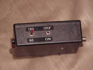
Here is a picture of a 60/180 notched amplifier circuit we made for our own field work(when we are not using the spectrum analyzer).
Comparing readings between 60 and 180 gives you a rough idea of the predominant magnetic field frequency component:)

MVC-003S-1.jpg
 

karl riley

Senior Member
Pierre, that's interesting. That was the idea of my switcheable 20/25 sensor. It switched between a coil tuned to read 60 Hz correctly (with linear response to harmonics) to the same coil with components which made it read 60 and 180 Hz correctly, damping out higher harmonics. The use was the same as yours (but a much smaller sensor box!).

Karl
 
Status
Not open for further replies.
Top