Elevator shunt supervision

Status
Not open for further replies.

Steeno

New member
Location
Appleton WI
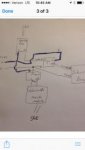
I'm tasked with wiring a supervisory circuit for a shunt trip to an elevator controller.
I have a 120v circuit for my shunt trip.
I need to wire this thru the elevator disconnect interlock contacts...and to the controller. The idea is the controller wants to know if the disconnect is turned off....the shunt is activated...or that 120v loses power ie breaker is off or loses power.

The shunt is activated by a relay on my fire alarm system activated by the heat detector in the machine room.
Any idea how to wire that circuit thru? I figure the contacts on the controller is simply wired in series thru the circuit...then to the controller. Not sure how to wire it up at the shunt / power source level tho.
 
Check out the System Sensor EOLR-1, web page located here. The coil is energized by the power you are monitoring. On the output side you put an addressable monitor module to pick up the state change if the power drops out.
 
Depending your disco. Will have a microswitch to show the on/off position too.

Depending on the distance between the disco and the shunt mechanism, you might want to monitor at the shunt. Something could happen to the conductors between the disco and the shunt breaker. Again, depends on distance, but I always feel better if the source voltage is "talking" as directly as possible to the fire alarm device.
 
If you are an electrician then you bring power for the elevator and a shunt trip into the elevator control room and you let the elevator guys take over.

I would agree that's usually best.

There are also requirements to monitor the shunt trip voltage. There also has to be a delay to allow the elevator to reach a recall landing before you shunt trip the power, and a signal to the elevator controller to tell it to go to a recall landing.

You don't want to trap people inside the elevator at the first sign of a fire.

Unless this is a local requirement, this is not true as far as I know. As soon as the heat detector in the machine room or hoistway activates, power is cut to the elevator.
 
Unless this is a local requirement, this is not true as far as I know. As soon as the heat detector in the machine room or hoistway activates, power is cut to the elevator.

Edit:

You are right. I'm getting local requirements confused with national standards. Here is a summary of the typical requirements;

http://rpsa-fire.com/documents_open/Elevator_Recall-Shutdown_rpsa_2010_rev_5.pdf

There seem to be so many requirements. That's why I think its usually better to let the elevator people handle the control logic and provide an output for the shunt trip.
 
Last edited:
Edit:

You are right. I'm getting local requirements confused with national standards. Here is a summary of the typical requirements;

http://rpsa-fire.com/documents_open/Elevator_Recall-Shutdown_rpsa_2010_rev_5.pdf

There seem to be so many requirements. That's why I think its usually better to let the elevator people handle the control logic and provide an output for the shunt trip.

Yes, usually the standard design I use is four control modules; primary recall, secondary recall, fireman's hat, and shunt trip. I have the elevator contractor locate his control panel and coordinate a location within 36" for my modules.
 
Maybe I can help.

Maybe I can help.

Typically, our state requires the elevator to shunt prior to the machine room or at the source. I can’t recall ever shunting at the controller.

I’m curious why the controller would need to know if the shunt has been activated....a loss of power would prevent the controller from functioning with the exception of “battery lowering”. Regardless, we use a 12/3 MC, black conductor to supply 120v to the relay module and the red conductor as a “switch leg” to provide 120v back to the elevator shunt trip breaker.

I’ve included our typical shunt trip wiring diagram. As stated in other replies, that 120v needs to be monitored for power loss. That should just be a supervisory condition that alerts the Fire Alarm monitoring company of power loss so it can be corrected. The diagram is a little rough but it’s one that every one of our electricians (who have a Fire Alarm license) carry on their phone. Take note that it was drawn using the Normally Open (NO) set of contacts on the center PAM-1 relay, that is not correct. It is darkened to look like a “C” indicating the need to use the Normally Closed (NC) contacts.

I’m hoping this helps. 2C0C2DD0-6FA8-414B-A78C-598AC45FC232.jpg
 

Attachments

  • D93419BF-5471-4865-848A-FAA14F8DB2B8.jpg
    D93419BF-5471-4865-848A-FAA14F8DB2B8.jpg
    5.2 KB · Views: 43
Status
Not open for further replies.
Top