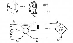
I am using the enphase branded combiner box for an enphase system. It houses the monitoring device which requires a neutral.
My question is about the size of this neutral. As far as I know it is only being used for one thing, the electronics inside the box. So am i allowed to downsize it to a 14awg wire since the controls circuit is is 15amp?
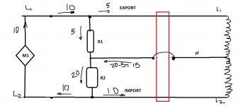
That would mean if I am backfeeding, say 50 amps to the main panel I would run my two larger L1+L2 with a smaller neutral. Is this allowed?
I am sure there is a code section on this, thanks
My question is about the size of this neutral. As far as I know it is only being used for one thing, the electronics inside the box. So am i allowed to downsize it to a 14awg wire since the controls circuit is is 15amp?
That would mean if I am backfeeding, say 50 amps to the main panel I would run my two larger L1+L2 with a smaller neutral. Is this allowed?
I am sure there is a code section on this, thanks