Explanation of UPS battery voltages

Status
Not open for further replies.

Twoskinsoneman

Senior Member
Location
West Virginia, USA NEC: 2020
Occupation
Facility Senior Electrician
I was talking to a tech the other day and he told me when he was doing a PM to check the cells of each battery in a UPS string he got shocked when his arm was in contact with one of the battery terminals and the rack that hold the batteries. Out of curiosity I took some reading and was hoping one of you geniuses could tell me what I'm seeing. It is an Eaton 9315 500kVa 480v UPS. It has a string of batteries, 2.75 volts per cell 240 cells. I figured if the string were grounded on the negative side you could get shocked between the rack and any number of the battery terminals once the potential was high enough. What I found has me baffled a little though.
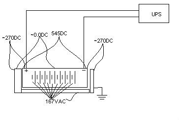
From the positive wire to the negative 540vdc, 0vac
From either positive or negative to ground ~270vdc, 167vac
From the "middle" cell to ground 0vdc, 167vac (this is real voltage measured with a low-impedance path)
From various cells there is an accumulative dc voltage to ground, further from the middle cell the higher the potential to ground.
From every cell there is 167vac to ground.

There is no connection from the battery string to ground unless it's in the UPS which I did not open up. I guess since there is 0vdc from the "middle" cell to ground I was looking for some connection to ground at that cell but there is none.

Where might the indicated 167vac be coming from?
Why would the middle of the battery string be indicating 0.0vdc?

Thanks

Oh, here is a crappy paint drawing to help a little. Obviously there are more cells than shown.
upsbat.jpg
 

Twoskinsoneman

Senior Member
Location
West Virginia, USA NEC: 2020
Occupation
Facility Senior Electrician
I'm not sure there IS a problem. In fact I highly doubt it. There are two identical 500kva systems and the voltage readings are the same on both systems.
Also one system just had a major repair. The SCR module, control board, and all six inverters were replaced less than a week ago. :D

I don't think there is a problem, I just don't quite understand the voltages I'm seeing.
 

massfd

Member
I think it's normal, think about it you have SCR's (or what ever switching device the UPS uses) connecting the batterys to the AC load. While they may only be turned on for MS at a time to simulate a sine wave they are still connecting the battery buss to the AC load. The AC load may be thru sub panel with a neutral to ground bond.

The 10kva Liebert we have has a 230V battery buss and does have a similar voltage from the DC to ground.

It could also be leakage current from an output isolation Xformer, 5ma and you will feel it much more and your dead.

I warn anyone who works on UPS's that even shut down they can KILL
 

Twoskinsoneman

Senior Member
Location
West Virginia, USA NEC: 2020
Occupation
Facility Senior Electrician
I think it's normal, think about it you have SCR's (or what ever switching device the UPS uses) connecting the batterys to the AC load. While they may only be turned on for MS at a time to simulate a sine wave they are still connecting the battery buss to the AC load. The AC load may be thru sub panel with a neutral to ground bond.

It could also be leakage current from an output isolation Xformer, 5ma and you will feel it much more and your dead.

It sounds like your saying that when the inverters are creating the AC voltage it can back feed back to the batteries but this doesn't seem possible.
 

hurk27

Senior Member
It sounds like your saying that when the inverters are creating the AC voltage it can back feed back to the batteries but this doesn't seem possible.

Could it be ripple current that is showing up on a AC meter, switch mode inverters will produce ripple on the DC buss at 120hz for single phase and 180hz 3-phase although it should be much lower then the readings he is getting, but then a AC voltage meter tuned to read at 60hz, can read higher at higher frequencies?

What about phantom voltage?
 

__dan

Senior Member
I have no explanation but will throw a few guesses at you. The Eaton factory engineer will have a much beter understanding of what is happening inside the UPS.

It's a good bet that the reference to ground is being provided somewhere inside the UPS, either at the rectifier or inverter, probably by the banks of filter caps. The paralled filter cap arrays may be arranged in series to limit the voltage across the individual caps to extend cap lifetime. The individual caps could be working at 270 volt instead of line to line at 540 volt and somewhere in the DC bus circuit is a ground reference, midpoint of caps in series, through an impedance or a busbar, creating a ground reference at the midpoint of the voltage and + 270, -270 DC volts to ground at the meter. This is done to limit voltage stress on insulating materials and limit the working voltage of the caps.

The AC voltage at 167 volts, my first thought would be an artifact of the measuring tool and not truly a 167 volt sinewave. What I would expect should be there is the DC float voltage and a minimum of AC ripple. You indicate 540 VDC and 0 VAC which is great.

The DC 0 volt battery bank midpoint measuring 167 VAC to ground, if this is confirmed by independent instruments, reading the same on both a true RMS type (Fluke 87), and a Wiggy type low impedance meter, this indicates to me that the UPS internal ground reference is through an impedance and not through a busbar. It is not pinned or bolted to ground.

It's very possible that the design, factory engineering, allows the DC bus midpoint voltage to do something wierd like wobble at 167 VAC RMS around the external earth ground reference. This would be a single point connection to earth through an impedance so no current would flow at 167 VAC. A call to a factory engneer should immediately confirm if this is normal and expected.
 
Status
Not open for further replies.
Top