Filling Out Panel Schedules

Status
Not open for further replies.

Keri_WW

Senior Member
Hi everyone!

I'm starting to learn about electrical consulting type work for commercial buildings and such and have been getting a little hung up on filling out my panel schedules. I'm used to having, let's say, a 208/1 phase load and just putting the entire load centered between the A/B phase. The company I am co-oping with doesn't show it that way...they show values for each phase. I hope that makes sense!

So here's my question, if I have 5kVA of load at 208/1, do I show that as 2.5k per phase A and 2.5k per phase B, and for 3 phase I would just divide by 3? I'm sure I'm over complicating this, but I want to make sure I do the best I can here.

Thanks so much!! :grin: :grin:
Keri
 
That's what we do. Be sure you're using the equipment's rated load at the voltage you're supplying for line-to-line loads.
 
Which value do you put in for the load? Running Load Amps, Minimum Circuit Amps, or Full Load Amps? I understand FLA and MCA and their use in calculating the overcurrent protection, but what is RLA used for?

Thanks!! :grin: :grin:
Keri
 
Keri_WW said:
So here's my question, if I have 5kVA of load at 208/1, do I show that as 2.5k per phase A and 2.5k per phase B, and for 3 phase I would just divide by 3? I'm sure I'm over complicating this, but I want to make sure I do the best I can here.
You'll spread your 5kVA load over each hot leg, so in this case (2) legs.
 
Keri_WW said:
Which value do you put in for the load? Running Load Amps, Minimum Circuit Amps, or Full Load Amps? I understand FLA and MCA and their use in calculating the overcurrent protection, but what is RLA used for?
First: In 16 years of consulting, I've never used RLA. That's not to say don't do it, but I never have.

Second: Do you need to show the amperage for each load? I've always indicated kVA thru the entire schedule then at the bottom total all loads then show overall amperage per leg - in other words (1) amerage value per leg, that's it.

Your motors ought to be scheduled somewhere and FLA or MCA or whatever indicated there - I wouldn't duplicate that information at all. Your transformers are a function of the loads they serve and I'd only indicate connected kVA.

Hope that makes sense.

Just my $0.02 - and 2 cents ain't worth but 2 cents.
 
Keri_WW said:
... if I have 5kVA of load at 208/1, do I show that as 2.5k per phase A and 2.5k per phase B, ...

Single phase loads (i.e. two pole) on a three phase panel, have issues with how current is figured. Therefore, a single phase load on a three phase panel should be shown as 5KVA, in this case on Phase A, with Phase B, dashed out. It is not appropriate to show it equally divided between phases. This may present some issues with the format of the panel scehdule you are using, but that is another problem in itself.
 
kingpb said:
Therefore, a single phase load on a three phase panel should be shown as 5KVA, in this case on Phase A, with Phase B, dashed out. It is not appropriate to show it equally divided between phases.
Why not? Each leg "sees" the load. I'm truly curious.
 
831 said:
Why not? Each leg "sees" the load. I'm truly curious.

DISCLAIMER: "Assuming the effect of having and unbalanced load is inconsequential"....


Given:
208Y/120V panel and a 1000VA resistive heating load, the current is correctly calculated by -

1000VA/208V = 4.83A

If, you were to divide the 1000VA load evenly between phase A and B (500VA ea) it would indicate the the voltage is now 120V with a 500VA load on each phase, and the current would incorrectly be calculated as -

500VA/120V = 4.17A

The proof that the second method is incorrect lies in the fact that a 1000VA is 1000VA and it cannot have two different values of rated current.

The reason behind this can be explained by the fact that on a three phase panel, there is a difference of 1.732 (sqrt 3) between the line to line voltage and the line to neutral voltage, e.g. 208V/1.732 = 120V, which does not occur on a single phase panel, i.e. 120/240V where the ratio is 2;1 from HV to LV.

Refer to calculations as follows:

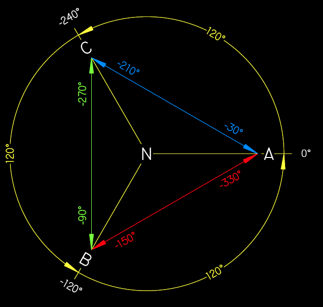
View attachment 671

Hope the resolves your question.
 
kingpb said:
Hope the resolves your question.
While I concur with the reasoning, I disagree with...
...a single phase load on a three phase panel should be shown as 5KVA, in this case on Phase A, with Phase B, dashed out.
...and lean towards...
Keri_WW said:
I'm used to having, let's say, a 208/1 phase load and just putting the entire load centered between the A/B phase.
However, both lead to a problem in the column totals. Any suggestions on how to resolve that?
 
Certainly putting it between the two phases is an option, just not one that seems very viable, given the fact that most panel schedules are using either a database or spreadsheet that requires input into a single cell. The one's I have seen are putting it in the first phase, and using the number pf poles designator of 1, 2, or 3 to initiate the logic for doing the calculation.

If the panel schedule is simply a graphical representation, without any formulas or calculations being performed, then I can see the value in putting the load in between.
 
kingpb said:
DISCLAIMER: "Assuming the effect of having and unbalanced load is inconsequential"....


Given:
208Y/120V panel and a 1000VA resistive heating load, the current is correctly calculated by -

1000VA/208V = 4.83A

If, you were to divide the 1000VA load evenly between phase A and B (500VA ea) it would indicate the the voltage is now 120V with a 500VA load on each phase, and the current would incorrectly be calculated as -

500VA/120V = 4.17A

The proof that the second method is incorrect lies in the fact that a 1000VA is 1000VA and it cannot have two different values of rated current.

The reason behind this can be explained by the fact that on a three phase panel, there is a difference of 1.732 (sqrt 3) between the line to line voltage and the line to neutral voltage, e.g. 208V/1.732 = 120V, which does not occur on a single phase panel, i.e. 120/240V where the ratio is 2;1 from HV to LV.

Refer to calculations as follows:

View attachment 671

Hope the resolves your question.
I guess I should have been more clear in my initial reply. B phase does/will see load as does A. I don't/can't disagree w/ your math, but B does in fact see load, so I'd show it. I guess it's just another way of doing a panel schedule. I was looking @ one yesterday where a consultant had done something I've never seen and it took me like 15 minutes to figure out, but in the end it (there work) was right.
 
Why not? Each leg "sees" the load. I'm truly curious.

DISCLAIMER: "Assuming the effect of having and unbalanced load is inconsequential"....

This disclaimer avoids the root of the question.

You should show each load on the correct phase. If its a 500VA single pole load on circuit 1, show it on all on phase A. Do this for every load in the panel. Divide 2 pole loads between the two phases you put them on. Divide three pole loads between all three phases. When the entire panel is filled out, then total up all three phases. If the three phases are fairly balanced then the underlying assuptions for the following calculations are still valid. (If they are not balanced, the calcs are really not correct. You should re-arrange the loads to get them more ballanced.)

Lastly, add A, B, & C phase totals to get one total va for the panel. Divide by 208 * 1.73 and thats the demand current for the panel.

The more unbalanced your three loads are the more incorrect this number will be.

Your statement that each leg sees the load is incorrect. Each leg see only the load that is connected to it. Unballanced current flows in the neutral. It seems like each leg sees the load because of how we do the math. In realty, everyone just divides by 360 to get the load but in doing this we are assuming the load is balanced.

This brings me to another thought. We can never really balance a panel because we never know which loads are on at any given time. You can spend a lot of time re-arranging your loads to get your panels to balance perfectly but this will only every be accurate if every light, and outlet, and A/C fed from the panel is on at the same time. The best compromise may be to try to get all three phase to within about 10% of each other and then move on.
 
kingpb said:
Certainly putting it between the two phases is an option, just not one that seems very viable, given the fact that most panel schedules are using either a database or spreadsheet that requires input into a single cell. The one's I have seen are putting it in the first phase, and using the number pf poles designator of 1, 2, or 3 to initiate the logic for doing the calculation.
This is along the lines that I have contemplated doing for some time in an Excel spreadsheet, but I want to take it to the degree where choosing a two-pole "designator" would put the data into merged cells, where it appears connected to both lines and totalled separate from, then calculated with 1 and 3? loads appropriately. In attempting the above, I discovered it requires a better working knowledge of macros and/or scripting than I currently posess :-?
 
sceepe said:
This disclaimer avoids the root of the question.

You should show each load on the correct phase. If its a 500VA single pole load on circuit 1, show it on all on phase A. Do this for every load in the panel. Divide 2 pole loads between the two phases you put them on. Divide three pole loads between all three phases. When the entire panel is filled out, then total up all three phases. If the three phases are fairly balanced then the underlying assuptions for the following calculations are still valid. (If they are not balanced, the calcs are really not correct. You should re-arrange the loads to get them more ballanced.)

Lastly, add A, B, & C phase totals to get one total va for the panel. Divide by 208 * 1.73 and thats the demand current for the panel.

The more unbalanced your three loads are the more incorrect this number will be.
The problem, perhaps trivial in some eyes, is using this method can give an appearance of having a balanced panel... yet it is not. For example:
Code:
			A	B	C
500KVA 1? 1P load	500		
1000KVA 1? 2P load		500	
					500
1500KVA 3? load		500		
				500	
					500
		Totals	1000	1000	1000

Apparent amperes/line	8.33	8.33	8.33
Actual amperes/line	8.33	8.68	8.68

Your statement that each leg sees the load is incorrect.
I believe 831 was referring to "each leg" that the two-pole load is connected to. :rolleyes:
 
Smart $ said:
The problem, perhaps trivial in some eyes, is using this method can give an appearance of having a balanced panel... yet it is not. For example:
Code:
            A    B    C
500KVA 1? 1P load    500        
1000KVA 1? 2P load        500    
                    500
1500KVA 3? load        500        
                500    
                    500
        Totals    1000    1000    1000
 
Apparent amperes/line    8.33    8.33    8.33
Actual amperes/line    8.33    8.68    8.68

Smart$,

I see how you came up with the apparent amps, but when I calculated the actual amps I came up with 8.97 instead of 8.68.

There must be some phase angle thing I'm missing. Could you explain in laymans terms?

Thanks,
 
hardworkingstiff said:
Smart$,

I see how you came up with the apparent amps, but when I calculated the actual amps I came up with 8.97 instead of 8.68.

There must be some phase angle thing I'm missing. Could you explain in laymans terms?

Thanks,

Use significant figures and its 9 amperes anyway! Your both right.
 
hardworkingstiff said:
Smart$,

I see how you came up with the apparent amps, but when I calculated the actual amps I came up with 8.97 instead of 8.68.

There must be some phase angle thing I'm missing. Could you explain in laymans terms?

Thanks,
Single pole (1? L-N) and [balanced] three pole (3? L-L-L) load currents are in phase with line-to-neutral voltage (resistive-only circuits). Two pole voltages and currents are, however, 30? out of phase with line-to-neutral voltage...

angles.gif


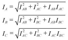
The formulas I posted earlier in another thread (and below) are only for calculating the combined current of two pole loads.

linecurrent.gif


To calculate the combined current of an in-phase current and one which is 30? out, we have to revisit the law of cosines. Therefore, the equation would be:
Iline = √(a? + b? - 2ab cos150?)​
Since cos150? = -0.866 = -(√3)/2, the formula becomes:
Iline = √(a? + b? + ab√3)​
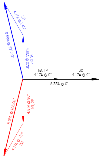
Calculating our load currents we get:
1500VA ? 3 ? 120V = 4.17A, and
1000VA ? 208 = 4.81A​
Using our new formula:
Iline = √(4.17A? + 4.81A? + 4.17A ? 4.81A ? √3) = 8.68A​
...or we can do it graphically with vectors:

actualcurrent.gif
 
Last edited:
Wow. Great graphics Smart$! Thanks for that. What did you use to create that? I tried to paste an ACAD drawing but it didn't turn out.
 
Status
Not open for further replies.
Top