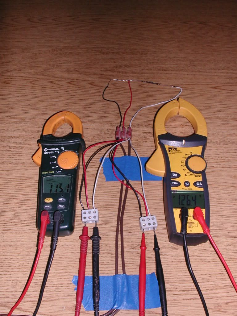
Forum members never cease to amaze me

Status
Not open for further replies.

chris kennedy

Senior Member
Location
Miami Fla.
Occupation
60 yr old tool twisting electrician
In response to this thread, I received this in the mail from gar.
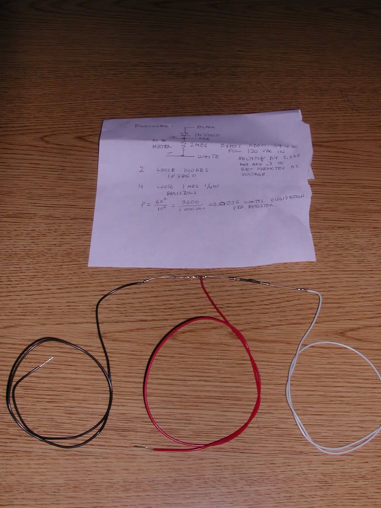
betatronics.jpg


This is both meters on AC voltage.

betatronics001.jpg


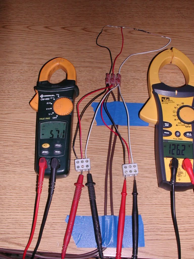
This is Greenlee on AC voltage and Ideal on DC voltage.
betatronics002.jpg


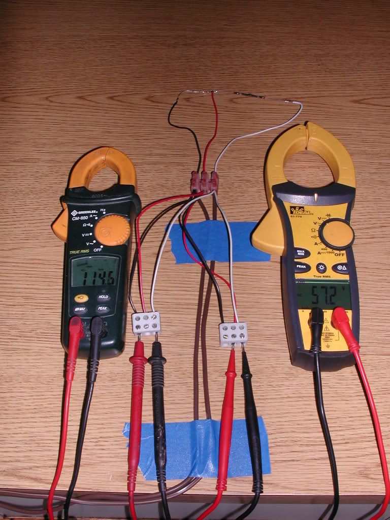
And Ideal on AC and Greenlee on DC.

betatronics004.jpg


Gordon, I can't thank you enough as I love an experiment, but I have no idea what these results prove.
 

LarryFine

Master Electrician Electric Contractor Richmond VA
Location
Henrico County, VA
Occupation
Electrical Contractor
Why does the physical wiring set-up not look like the diagram on the paper?
It does: black to diode, white to resistor, red to center point. Meter to be connected to black and white to measure line AC, and to red and white for rectified DC voltage.

Note the terminals used for the meter test probes in each picture.

If this were a half-wave power supply, the resistor would be replaced by (or paralleled with) a filter capacitor.
 

480sparky

Senior Member
Location
Iowegia
It does to me??? But I have to say, I turned my head when I plugged that thing in.:D

Did you done proper arc-flash gear?

I see it came with instructions. It is UL listed?
themot-roflolmao.gif


It does: black to diode, white to resistor, red to center point. Meter to be connected to black and white to measure line AC, and to red and white for rectified DC voltage.

If this were a half-wave power supply, the resistor would be replaced by (or paralleled with) a filter capacitor.

I see two things between the red and white.
 

chris kennedy

Senior Member
Location
Miami Fla.
Occupation
60 yr old tool twisting electrician
It does: black to diode, white to resistor, red to center point. Meter to be connected to black and white to measure line AC, and to red and white for rectified DC voltage.

Note the terminals used for the meter test probes in each picture.

If this were a half-wave power supply, the resistor would be replaced by (or paralleled with) a filter capacitor.

Larry, can you tell from the results if one or both meters is out of wack?
 

480sparky

Senior Member
Location
Iowegia
That's because he drew where to place the meter leads for DC testing.

Even 10 wires meeting at a point (or node) is still just one point.

You're net getting it.

I see one resistor (2 megohms)in the wiring diagram. I see two in the actual item. Unless it's two 1-megohm resistors, there's a discrepency twixt the two.
 

LarryFine

Master Electrician Electric Contractor Richmond VA
Location
Henrico County, VA
Occupation
Electrical Contractor
You're net getting it.

I see one resistor (2 megohms)in the wiring diagram. I see two in the actual item. Unless it's two 1-megohm resistors, there's a discrepency twixt the two.
Well, I see two resistors with what appears to be heat-shrink between them, so I agree that they to be a pair of 1M resistors.

They're obviously in series, so to the circuit, they comprise a single element of that circuit. They don't change the circuit itself.
 

iaov

Senior Member
Location
Rhinelander WI
Its almost the same picture you had the other day Chris with the two meters showing different voltages. At least one of them is wrong!! I'm not sure what the picture with the DC voltage is about. Most AC voltmeters are pretty close usually. PH meters used to drive me crazy!:mad:
 

mark32

Senior Member
Location
Currently in NJ
I formerly worked at a shop that built pressure washers in which I wired their electric models. After assembly they were tested and an amp reading was recorded using the same model Greenlee tester shown above. One day I noticed strange voltage readings in the building. I mentioned it to the shop super but this went on for a couple of days when we finally called out the power company to investigate, they found nothing wrong. The next day we threw in some fresh batteries and normal voltage readings returned. Doh!
 
Larry, can you tell from the results if one or both meters is out of wack?

I'm not Larry, but it looks to me that the Greenlee is out of wack on AC readings.

On the note, GAR said to expect about 54vdc reading to match up with about 120vac. Your VDC readings on both meters line up at about 57 volts, which means your AC voltage should be over 120v. The ideal gives you VAC over 120, the green lee does not.

That's all based on logic, not actually doing the math, so please feel free to tell me I'm wrong :grin:
 

LarryFine

Master Electrician Electric Contractor Richmond VA
Location
Henrico County, VA
Occupation
Electrical Contractor
I'm not Larry, but it looks to me that the Greenlee is out of wack on AC readings.
I'm not Larry either, but I did stay at a Holiday Inn last night.

That's all based on logic, not actually doing the math, so please feel free to tell me I'm wrong :grin:
I can't, because I agree with you. :smile:
 

Rick Christopherson

Senior Member
Chris, I am flattered that you asked me to look into this, but I am sure there are others on this forum that have a much deeper expertise in this area than me.

I am just taking a wild stab at this, but I suspect your Greenlee meter has lost rectification. They both read accurately at DC, and in this case, they both read accurately at partial DC. Because you added an external diode and suddenly got agreement between the two meters, it indicates that you have compensated for a lost diode internal to the meter.

If you reverse polarity on your probes and the result changes (no longer giving consistent readings) then this would confirm my suspicion. If you lose rectification on the meter, it stands to reason that it will be reading lower than actual value. (Like reading an AC signal with the meter set to DC, it will read near zero.)

================================
By the way, from your hair dryer experiment, I am surprised that no one noticed that the two readings were still proportional, with the Greenlee being consistently low by a factor of 1.1 for both voltage readings and the amperage reading.

V1 / V2 = A1 / A2

This is consistent with the above reasoning.
 

quogueelectric

Senior Member
Location
new york
Gar is awesome I cant even tell you he is the bonb what a nice guy!! Not many out there as stand up as him. He is the true renaisance man looking for the truth and helping others to achieve the same. Thanks GAR I got a package from him last week. He has no hidden agendas.
 

ohmhead

Senior Member
Location
ORLANDO FLA
Well just a point the first picture i disagree with the selector switch on the meters there both on ac power sorry . The circuit is a simple voltage divider circuit yes it has a diode or two i only see one actual diode used with the resistors used and looking at the voltage i dont see a problem with the meters they may be out of calibration but if you look its a voltage divider circuit so yes voltage is cut by half or so due to resistance and diode or diodes . You have a loss in the diodes when they conduct they drop a volt kind of and voltage drop across the resistors is what you are looking at not a meter problem its a VOLTAGE DROP across the load. i think both meters are fine its the connection to the circuits and good meter to bad meter is how its calibrated or who makes it ! fluke is the only meter . comments take care
 
Status
Not open for further replies.
Top