Friday's Failure Forum Picture

Status
Not open for further replies.

ghostbuster

Senior Member
MVC-002S.jpg


Location:Large T.V. Broadcasting Studio

Facts

1.Video hum bars on video signal preventing broadcasting
2.Found 10-15 amps of ground current flowing on broadcast system
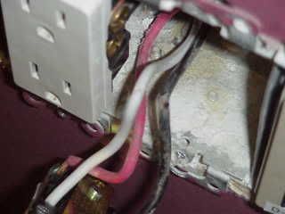
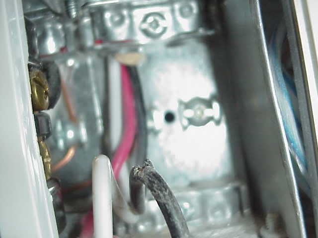
3.Found neutral wiring accidentally shorted to case ground.Sharp metal edges inside box had nicked hot and neutral wiring.(neutral had grounded out)
4.Note: no loads plugged into this receptacle at the time but system neutral solidly shorted to ground within this electrical box.

Corrective Measures:
1. Wiring repaired,video hum bars disappeared,TV station now able to broadcast.
:) :)
 
Used to be real common around these parts that 3wire NM cable was used & the red was the eq grd. I still see it alot when I T/S older bldgs. I was told by an older timer than me (imagine that) that the NM didn't have a bare eq grd or that the bare wire was that #16 or #18 undersized wire so to get a full sized eq ground they used the red.
 
davidr43229 said:
how the heck, did you ever find that ?

David
This was a 4000 amp service.Essentially,you start at the main feeder and use net current measurements to determine what sub feeds need to be examined more closely.You keep going down each sub/sub/sub feed until the problem is uncovered.

George and Celtic

Yes,the red conductor is connected to ground.Back at the J box it connects to the green conductor.
I have enclosed a full size picture(another angle) of this wiring.
MVC-003S.jpg

:)
 
bkludecke said:
I was told by an older timer than me (imagine that) that the NM didn't have a bare eq grd or that the bare wire was that #16 or #18 undersized wire so to get a full sized eq ground they used the red.
Bob,

I was apprenticing with that wire, in my summers between engine school.

The reduced size EGC was insulated some of the time with little more than doorbell wire insulation. . .but it was green. It definitely wasn't a 600V or even a 300V insulation.

The insulation on the EGC was a branding thing done by some manufacturers. Other manufacturers made their cable without insulation on the EGC.

The reduced size of the EGC was a manufacturer wide standard for roughly three Code cycles as the installation techniques were introduced to all installers. I say roughly three Code cycles 'cause what actually happened on the ground had a lot to do with how local jurisdictions adopted the 1962 NEC requirement that all receptacles be of the "grounding type".
 
Ghostbuster,

I can see that the cable is AC. The box clamp has the bushed retainer in it that holds the anti-short bushing in place.

My comments about NM are off the subject of your opening post.

It makes sense that the red would be a way to get a full sized EGC in a cable that, in my opinion, has a less than ideal equipment ground path through the spiral sheath and drain wire.
 
steve66 said:
Why is the neutral black?

That leaves white for the hot?

Steve

The OP said that both the neutral and hot were compromised but the neutral was grounded out not the hot. That was my understanding.

Also we use to use AC cable with 3 wires all the time in Kingston, NY for IBM.. but if I remember correctly we had to strip the red wire. IBM required a real ground so we couldn't rely on the cable steel.
 
shockme77 said:
This is a classic case of objectional current flow. And the low voltage television equipment that is required to be bonded had in effect become ungrounded. Correct?

Shockme
Not really.Check out derekbc's excellent dissertation on this subject in this forum group feb 10/07-entitled "audio recording circuit"

I have included a small sample below

Ghostbuster


Quote:
Originally Posted by dbuckley
The AC power that goes into a <fill in piece of audio equipment here> goes straight into a transformer, the primary of which has no reference in the equipment to to ground
Incorrect, input transformers are not used, haven't for the last 15 yesrs, they use switch mode power supplies. Any switch mode rectifies line voltage directly to DC, converts to high frequency AC, then into a transformer/rectifier circuit to derive the various DC voltages used by the equipment. But for the sake of argument lets say they do use an input transformer, the AC line is referenced to ground, why, there is a nuetral involved. In addition you have line input filters installed between L-G and N-G that discharge right into the chassis ground.

Either a isolation transformer or balanced transformer removes all noise from the line as they both are the same thing just tapped differently.

I agree most problems are eliminated by proper wiring techniques, but not common mode noise. Only device capable of effectively removing common mode noise is either an isolation transformer, motor-generator, or dual conversion UPS.

The safety problems involved with 120/60 systems are addressed in the code. Both phase conductors have to have OCPD and GFCI receptacles. In the case of the plug-n-play systems, all that is built into the box.

I am not advocating that balanced power is the only answer, it is the last resort. As Brian stated start with dedicated circuits, insure all the wiring of the facility meets code, and if that fails start taking steps.

Most of the noise like hum is caused by the equipment being sourced from multiple circuits that have small voltage differences induced onto the grounding conductors. These small voltage differences are picked up by the interconnected signal cables that use unbalanced transmission like coax where ground is used as a path. This is common mode noise.

There are lots of ways to deal with common mode noise like signal transformer, balanced signal lines, dedicated circuits, and isolation transformers. Start with the least expensive methods and work your way up. Personally I like optical, no problems.
__________________
Moderator

:) :)
 
ghostbuster said:
Most of the noise like hum is caused by the equipment being sourced from multiple circuits that have small voltage differences induced onto the grounding conductors. These small voltage differences are picked up by the interconnected signal cables that use unbalanced transmission like coax where ground is used as a path. This is common mode noise.
This is where IG for circuits may have come into being. If separate circuits power pieces of equipment that have interconnecting conductors that are connected to chassis at both ends, we get ground loops.

We know from experience that "a ground is a ground is a ground" is not necessarily so. I know of a pair of buildings that were built consecutively, and the second's temporary power was supplied through the first.

It was discovered through a hot temp feeder cable that interconnected the two buildings' EGC systems that there was around 20v difference bewteen them, which created enough current to get the EGC hot.

EGC systems are not always at zero volts to earth, but IG systems allow the equipment using them to all reference the same point (the service neutral-ground bonding point) instead of distant separate sub-panels.

One reason the IG is losing its benefits is that most data cabling these days is UTP, and not coaxial cables. Additionally, we often use balanced audio cabling (as opposed to coaxial) with the shield lifted at one end.

Think of an IG system as a large-scale star-grounding system. Ground loops are minimized by grounding everything at one point.
 
Larry,you should check out goldstar's cable "ground current thread" posted to-day in the contracting section.He is having "TV interference problems(bars and fuzzy problems)" even on simple home installations.I have copied a small section for you:::)


I'm just curious as to whether anyone else has run into this. I recently installed (6) CATV lines in someones house as well as ports and splitters. Everything seemed fine with clear pictures on all TV's. When the cable company came out to install boxes for their hi-def services thay advised the homeowner that they used an amp probe on the incoming CATV cable and there was more than 1 amp of current on the line and that their electrician had to correct it. Until that was corrected they would have bars and fuzzy lines running through their TV screens. They were correct.

I would never have thought to do this but I went back to the house and clamped onto the (underground) incoming CATV cable and sure enough I had over 1 amp of current. It went even higher when I removed the wiring going into the house. After re-grounding the outdoor connection port I managed to get the amperage down under 1 amp. I was unable to check whether the water main ground to the breaker panel was clean and not corroded because the homeowner sheetrocked the basement and buried the connection behind a wall. Other than that I can't think of anything else that might cause this problem. Any ideas ?

Thanks,

Phil
 
ghostbuster said:
Larry,you should check out goldstar's cable "ground current thread" posted to-day in the contracting section.
Phil, I did, and suggested a fix. Well, more of a band-aid, but it works most of the time.
 
Status
Not open for further replies.
Top