zemingduan
Senior Member
- Location
- Philadelphia,PA
- Occupation
- Electrical Designer
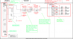
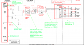
I am looking at the solar system drawings below and have two questions:
Q1: Do you need over current protection for the inverter output circuits as per 705.65?
Q2: Which are the line side and load side of this disconnect? Shall we reverse the disconnect switch and fuses? Code reference

Q1: Do you need over current protection for the inverter output circuits as per 705.65?
Q2: Which are the line side and load side of this disconnect? Shall we reverse the disconnect switch and fuses? Code reference