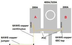
Does the picture show 250.62 (D)(1)(3): GEC tap to common electrode conductor via busbar connection? (This seems more like a jumper than a tap.)
Second question: If a separate GEC were run from each disconnect and both were clamped to a ground rod, you would still only need to run a single 6 AWG copper jumper from that ground rod to a second supplemental rod, right? (This is assuming a scenario where two are needed to achieve 25 ohms or less.)
Second question: If a separate GEC were run from each disconnect and both were clamped to a ground rod, you would still only need to run a single 6 AWG copper jumper from that ground rod to a second supplemental rod, right? (This is assuming a scenario where two are needed to achieve 25 ohms or less.)