Generac Sub Panel Transfer Switch Bonding

Location
Georgia
Occupation
Engineer
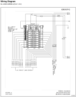
I had my Generac generator installed by a generator company, and something seems very wrong with their installation. It is using a 16 space/24 circuit sub-panel layout fed from a 100 amp breaker from the main panel (not a whole house switch). I noticed that there is only a single neutral/ground bar in the switch panel, which they have connected both neutrals and grounds to. Why would this be? Shouldn't there be separate ground and neutral buses? The panel uses Siemens guts and there is a place to snap in a 2nd bus rail, but it isn't there, just the one. There is also no place for a can mounted bar, just the snap in spot where on a regular Siemens panel would have a secondary neutral bar. Does this switch not follow the rules of a sub panel where ground and neutral should be unbonded?

The generator itself has a feed breaker, and the switch has no manual disconnect (it is fused though), I don't see anyway, or any scenario where this switch could be viewed as the first point of disconnect where neutral/ground bonding would be appropriate. It just seems very wrong. Seems like there should be a 2nd bar to separate the grounds from the neutrals and that the ground bar should then be bonded to the can, right?
 
It is using a 16 space/24 circuit sub-panel layout fed from a 100 amp breaker from the main panel (not a whole house switch). I noticed that there is only a single neutral/ground bar in the switch panel, which they have connected both neutrals and grounds to. Why would this be? Shouldn't there be separate ground and neutral buses?
This unfortunately is not unusual around here by some of the generator installers. Not to code. Not even on the first count it being a sub-panel. Bonding the N/G in the subpanel is a violation.
 
Do have some pics of the install?

Is what you are calling a “switch”, is it an ATS, MTS, critical circuit panel, breaker interlock? Something else?
It's an critical circuit ATS panel/switch. I don't have pictures though, and I'm not inclined to post any at the moment as I am in the process of trying to clean up the mess of wire nuts and splices the installers put in my main panel as well as replacing the PVC flex they also made a mess of. I am replacing it all with a raceway and moving all the splices to a big Millbank box with DIN rails. But given the current state I'd rather not post pics that, at the moment, are candidates for some "look at this scary electric" blog. I have my pride.

But anyway this is the manual for the switch:
Generac RXG16EZA1W

There is a surprising gloss over of anything about the grounds in that manual. Even the wiring diagram in my previous post, which is pulled from this Manual, just shows the grounds connected to the ground symbol, and not to any particular lug or bus. Also the panel/switch doesn't have enough locations to land just the base neutrals alone of the panel portion, if they were all single pole, let alone the 16-24 neutrals and 16-24 grounds (the panel is made to accommodate 8 tandems) without doubling or tripling up. If you bought the panel those guts are from directly from Siemens there are multiple, and larger neutral buses plus separate ground buses that can accommodate a maxed out panel with no shared landings and then some. The guts can accommodate even larger bars than that, large enough to land a full panels worth of grounds and neutrals, all single pole, individually, within the space of the plastic part on just 2 bars (as opposed to 4 in a complete panel). So not sure what Generac was thinking with that.

I will say though that the job the installers did is probably a version of what is described in that manual, a messy version, but not an unreasonable interpretation.
 
This unfortunately is not unusual around here by some of the generator installers. Not to code. Not even on the first count it being a sub-panel. Bonding the N/G in the subpanel is a violation.
Well that is kind of my thoughts, but the switch itself, as delivered, makes no accommodation for any other way. It has one bus bar, a too small bus bar for the panel in my personal opinion. It's not a main disconnect switch, by design, it's not even the primary disconnect for the generator itself as that has a disconnect breaker inside of it that disconnects the output, so I don't see how the transfer switch could even be viewed as the primary disconnect for an SDS. Which one would think bonding in that case would be required happen BEFORE that disconnect breaker. I mean I do plan to seperate them and make sure all GROUNDING is bonded the entire path, but I just don't see why you would sell a product that seems to violate the NEC just by how it's made. I mean this isn't some obscure product.
 
I pulled up the full manual on this model. This model is an Automatic Transfer for select circuits that are to be pulled from original panel and moved into the transfer panel. There is a single ground from the original panel brought forward into the transfer panel, and only required to be as big as the largest circuit with this panel it is likely provided in the whip with a #8Cu Meeting 250.122 minimum for 100A. Then all associated neutrals for the branch circuits come forward, there is a factory whip provided and the original circuits pass thru from the original terminations, spliced in the original panel. So you don't need every branch circuit ground brought forward into the transfer panel. If you need more neutral terminations they do have a 2 neutral bus transfer.
This transfer as designed cannot be used as a stand alone branch circuit transfer switch where the circuits don't pass through from a main panel.

Also this should have safety signage for both the transfer and the main panel as the transfer could be initiated by an electrical worker turning off the main breaker to presumably "make it safe" to work on and the generator comes on and transfer after a time delay. We're usually warned to look for alternative power sources when working on larger systems that almost always have some sort of "standby" system to avoid electrocution. Many shock and electrocutions happen this way. On the smaller residential systems most don't even think about that, thus the signage.
OK so, discounting that there is stipulations in the manual that you could just wire the circuits directly if necessary and there is no separate ground bus, it still remains that that grounding connector in the whip has no place to land but on the neutral bar. I don't see where if it's many or just one common EGC, at the end of the day it's a sub-panel, shouldn't the grounding conductor NOT be on the neutral bus bar?
 
OK so, discounting that there is stipulations in the manual that you could just wire the circuits directly if necessary and there is no separate ground bus, it still remains that that grounding connector in the whip has no place to land but on the neutral bar. I don't see where if it's many or just one common EGC, at the end of the day it's a sub-panel, shouldn't the grounding conductor NOT be on the neutral bus bar?
There is a single grounding termination associated with the transfer switch that is not in that one picture you provided. The enclosure itself is then bonded to the EGC back to the main panel, along with the 100A feed ungrounded conductors. The neutral is feed directly to the bus you are referencing in the image you provided..
 
Well, in reality there is a ground in the generator multi-cable and that lands on a lug bonded to the box, from the main panel to the switch panel there is a #3 neutral and a #4 ground that both terminate to the same bus in either panel. I honestly don't know at this point if that bus bar in the switch panel is bonded to the chassis, given how those internals bond in a normal Siemens panel, I assume not, there is no bonding screw. Also the switch panel and the main panel were connected with PVC flex so there was no metallic path between the 2 other than that #4 ground. All this will change soon as I am putting in a metallic raceway between the 2 panels, and will also be moving all the splices out of the main panel to a separate box, because my OCD just can't tolerate all those wire nuts and splices in the main panel. At that point
 
Top