Genset GEC and EGC

Status
Not open for further replies.
I'm a little confused in designing / installing the GEC and the EGC to avoid a parallel Ground Fault Path on a 150 KW Genset ( w/ OCP).

Here's the senerio:
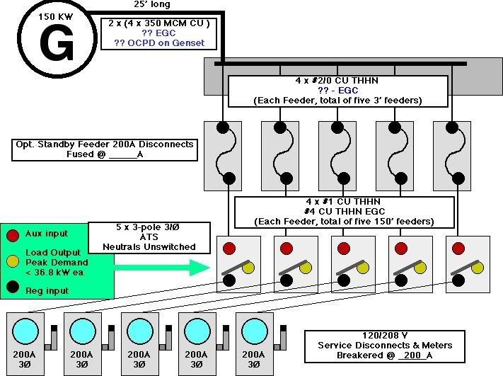
1. Facility has 5 - 3PH 200 A Meters/ Services feeding 5 tennant spaces.
2. 150 KW Genset w/ Main Breaker.
3. 5 - Exterior Mounted 200 A Fusible Disconnects.
4. 5 - Interior Mountred ATS's.

Here's my question.
Since the normal power nuetral is bonded at the Grounding Electrode at the main service ( 1000 Ft away) I will need to avoid any parallel Ground Fault Path when in Emergency Mode ( or normal mode for that matter).
I've installed EGC's w/ the feeders installed between ATS's and Fusable Disconnets ( S/N's on both), sized per Fuses in the Emergency System's Disconnects.
These disconects are feed from tap conductors in a wireway beneith them, tapped from parrallel 350's from the Genset w/ OCP.
I understand the nuetral bond with-in the genset must be removed.

Finally my issue:
1. Am I correct in assuming I do not need a GEC in this EMER system?
2. Am I correct in assuming that after disconnecting the Nuetral bond in the GenSet, I simply install EGC back to the genset and bond the frame, relying on the normal power GEC for Ground Fault Protection when in Emergency Mode?
3. And if so, how do I size the EGC from the Genset to the Wireway feeding the Disconects.

These are Art. 702 Loads
 
I use a 4 pole ATS to avoid a parralell path. However, from your statement you already have a 3-pole ATS for each tenant. I don't know if gensets come w/out a N-G bond in the genset ???????

Please Note a 150KW genset is approx giving you 490 amps @ 3ph 208V (.85 PF) for ALL tenants. Seems a little low.
 
Since you mentioned that you were removing the neutral to ground bond at the generator, I am assuming you are using a 3 pole ATS and not switching the neutral (grounded) conductor, which means the generator is connected as a non-SDS.

For #1) Therefore, using 2005 NEC 702.10(B), you would not need another GEC, but would need to bond the EGC to the system GEC at the normal power source.

For #2) I think you are correct.

For #3) I believe you would size the EGC's from the Genset to the fusible disconnects based on the rating of the fusible disconnects, although I am not sure on this part. Could be that you have to size it based on the rating of the main service OCP.
 
I agree with wire nut except for the size of EGC. Are you upsizing your parallel feeder conductors for VD if so then you have to increase the EGC by the same percent.
 
Reply

Reply

Thanx for your replys.

Addn'l info:
1. The Parallel 350's are only 25 FT in Length.
2. Feeders to ATS's are #1 THHN CU 4 X 150 FT.
3. Peak demand over a two year period never exceded 36.8 KW on the largest of the 5 loads (per utility).
4. I've currently installed #4 EGC in each of the 5 feeders serving the ATS's from the Fusible Disconnects.

I'm still leary in as far as the sizing of the EGC from the GenSet to the wireway. I have parallel 350's 25FT in lenght ea. from GenSet to the Wireway of which I have tapped w/ 2/0 conductors to the line side of each disconnect located 8" above the wireway. Then # 1 Cu on the load side of disconnects to the ATS's w/ #4 EGC.
System is 208/120V 3PH 4W
 
The answer to your riddle lies in your ATS. Is it 3 pole (not switching the neutral) or 4 pole (switching the neutral)?

If you are not switching the neutral , your system is not separately derived .Take a look at 250.20(D) fine print notes 1 and 2. FPN 2 directs you to 445.13 which in turn leads you back to 250.24(c), (not all of 250.24 just 250.24(c). This is basically saying that you must size your grounded conductor to safely carry any fault current imposed on it . Also if you are not switching the neutral you are not required to have a grounding electrode or a grounding electrode conductor,(at the generator) so sizing of these would be supplementary. One more very important thing to point out is that installing a system bonding jumper is not only a code violation it is very dangerous,you would have increased magnetic fields,objectional current on metal parts, and the serious risk of a shock or fire.

Now, if you are switching the neutral, 250.30 applies. By switching the neutral you have created a separatly derived system. I would suggest reading 250 in the 2005 NEC, especially 250.20,250.30,250.102,250.104, and 250.122 (hope I didn't leave anything out). In this case you are required to have a system bonding jumper installed as well as a GE and GEC. If you leave the SBJ out you will have no way of clearing a ground fault.

As far as sizing your EGC ,basically if it is on the load side of a fuse or circuit breaker, go to 250.122 and size it based on the rating of the OCPD. Also read 250.122(b) and(f) closely.As far as the GE and GEC are concerned they are 250.66, based on the phase conductors.

I hope I was able to help,

Ibew441dc

P.S. this is my first time on the forum ,and I think its very educational
 
Last edited:
adavey said:
I use a 4 pole ATS to avoid a parralell path. However, from your statement you already have a 3-pole ATS for each tenant. I don't know if gensets come w/out a N-G bond in the genset ???????

Please Note a 150KW genset is approx giving you 490 amps @ 3ph 208V (.85 PF) for ALL tenants. Seems a little low.

Thanx Adavey,
The GenSet was sized per a 2 year peak demand on each of the 5 services combined on the premises per our local utility records.
I have a policy not to compromise the electrical installation by installing equipment that just " meets code". I'd much rather install service equipment that is 150% -175% over the required NEC rating; in fact all our Gensets have 115% PF. Yes we pass the added cost on to our customers, however we tell them up front, that they are getting a better than required system.
Normally when our customers request a stand by system it is because of their potential losses in revenue if in fact there is a power outage.

Thanks again,
I'm just a little confused if I need a GEC on this emergency system. I dont believe I do, thus leaving me with the issue of how to size the EGC.
As U know the EGC is sized per OCP in most cases.
 
Thanx IBEW 441dc

Thanx IBEW 441dc

Yes,
I am using 3 pole ATS's and am not switching the nuetral.
I have sized the EGC from the 5- Disconects to the 5-ATS's per 250-122.
Now, the parallel 350's from the Gen Set to the Gutter beneith the 5 disconnects:
I've tap the PAR. 350's w/ 2/0 THHN to the line side of the Disconnects (Located 8" above the Gutter). After consideration of the OCP in each Disconect I subsequently reduced the feeders to each ATS to #1 THHN w/ #4 EG., to match the actual load served.

With 5 Service Rated Disconnects and 5 individual #4 EGC from each disconnect to 5 ATS's, AND knowing I do not need a GEC for the Emergency system, I ask:

How do I size the EGC from the Disconnects through the Gutter and back to t he GenSet??

THanx in Advance!
 
Design Electric Inc. said:
How do I size the EGC from the Disconnects through the Gutter and back to the GenSet??
You size the EGC according to 250.122, by the OCPD supplying the ungrounded conductors.

Does this look about right?

CommATSschema.jpg


What is the OCPD of the generator, and of the fuses in the disconnects?
 
Design Electric Inc. (original post) said:
2. Am I correct in assuming that after disconnecting the Nuetral bond in the GenSet, I simply install EGC back to the genset and bond the frame, relying on the normal power GEC for Ground Fault Protection when in Emergency Mode?
Design, welcome to the forum.

Are you are that the GEC/GES plays no role in the clearing of ground faults?
 
ibew441dc said:
The answer to your riddle lies in your ATS. Is it 3 pole (not switching the neutral) or 4 pole (switching the neutral)?

One more very important thing to point out is that installing a system bonding jumper is not only a code violation it is very dangerous,you would have increased magnetic fields,objectional current on metal parts, and the serious risk of a shock or fire.


Could you please explain this better. I think you are confused with this comment.
 
The danger would come from the Equipment Grounding Conductor carrying neutral current under open neutral conditions. Since it is sized only to clear a fault the voltage drop on the EGC would cause stray currents to flow on all sorts of metallic structural components. That would raise the touch potential of those surfaces to possibly dangerous levels.
 
Thanx Georgestoltz

Thanx Georgestoltz

Thanx George,
THis all seems so simple once the issue of the emergency system / genset GEC / GES was cleared. Since one is not required, the GEC sizing is elementary.
I appreciate the one line dia.
- The GenSet OCD is set at 630 A: we installed Par. 2/0 EGC w/ the 350's from the GenSet through the wireway and to each Disconnect.
- All Normal Power Feeders are Fused @ 200 A.
- All Standby Power Feeders are Fused @ 125A.
 
Design, you're welcome. :)

Let me clear up a few acronyms, because it's a little confusing as to whether we're on the same page. Each one means something a little different, and makes a big difference as to the function and the code references for each.
GES: Grounding Electrode System.
GEC: Grounding Electrode Conductor
EGC: Equipment Grounding Conductor

The conductors between the genset and the ATS's are EGC's. They carry fault current in the event of a ground fault (short to ground.)

- The GenSet OCD is set at 630 A:
You understand the conductor ampacity is 10A shy of that, don't you? Is the breaker adjustable?

Since the connected load is being figured around 511A, then you could use 240.4(B) to use parallel 300's and a 600A breaker. But I'm not quite sure how you can come around to a size bigger conductor not quite fully protected by the OCPD. Is this intentional or accidental?

we installed Par. 2/0 EGC w/ the 350's from the GenSet through the wireway and to each Disconnect.
Copper? Sounds good. :)

All in all, pretty tight, sounds good. :)
 
genset gec and egc

genset gec and egc

ibew441dc said:
The answer to your riddle lies in your ATS. Is it 3 pole (not switching the neutral) or 4 pole (switching the neutral)?

If you are not switching the neutral , your system is not separately derived .Take a look at 250.20(D) fine print notes 1 and 2. FPN 2 directs you to 445.13 which in turn leads you back to 250.24(c), (not all of 250.24 just 250.24(c). This is basically saying that you must size your grounded conductor to safely carry any fault current imposed on it . Also if you are not switching the neutral you are not required to have a grounding electrode or a grounding electrode conductor,(at the generator) so sizing of these would be supplementary. One more very important thing to point out is that installing a system bonding jumper is not only a code violation it is very dangerous,you would have increased magnetic fields,objectional current on metal parts, and the serious risk of a shock or fire.

Now, if you are switching the neutral, 250.30 applies. By switching the neutral you have created a separatly derived system. I would suggest reading 250 in the 2005 NEC, especially 250.20,250.30,250.102,250.104, and 250.122 (hope I didn't leave anything out). In this case you are required to have a system bonding jumper installed as well as a GE and GEC. If you leave the SBJ out you will have no way of clearing a ground fault.

As far as sizing your EGC ,basically if it is on the load side of a fuse or circuit breaker, go to 250.122 and size it based on the rating of the OCPD. Also read 250.122(b) and(f) closely.As far as the GE and GEC are concerned they are 250.66, based on the phase conductors.

I hope I was able to help,

Ibew441dc

P.S. this is my first time on the forum ,and I think its very educational


Pierre C Belarge

In all do respect, I feel that you are the one who is confused.

Please re-read what I posted and think about what I said.

You pointed out my comment about the system bonding jumper. Wouldn't you agree that if you had an ATS that wasn't switching the neutral, a normal power source , and a generator , that by installing , or not removing the system bonding jumper at the generator you would create a parallel path for neutral current.

If your with me up to this point , wouldn't you agree that it is not only dangerous (shock/fire hazard), but you would also have increased magnetic fields, causing interference on sensitive electronics .


I challenge you to draw a picture of two scenerios.
1. basic emergency set-up switching the neutral (4 pole ATS)
2. basic emergency set-up not switching the neutral (3 pole ATS)

(Assuming the entire system is wired correctly)
In scenario 2 since the main bonding jumper is installed at the service and you are not switching the neutral at the ATS there is a direct electrical connection between the service and the generator. This means that if you instal the system bonding jumper in this case you violate the NEC 2005 in a number of ways.

Here are a few, 250.6(A), 250.20(D) FPN1 and FPN2, 250.142(B)250.24(C)220.61


hope this clears it up some

Ibew441dc
 
Pierre C Belarge

I would really like to here your feed back on my last post.


Ibew441dc

Local 441 apprentice
 
Do you have a nickname or something? Your "handle" is a finger-twister. :D

While we wait for Pierre to respond, I have a question.

While the setup is illegal with the jumper in place and the neutral unswitched (which I don't think anyone is disputing), how would magnetic fields come about?

300.3 requires all conductors of a circuit to be in the same conduit (with exceptions). If all the conductors are in the same conduit, and neutral current is flowing on the EGC of the same pipe, and the current on the hots equal the current on the EGC and neutral combined, then there should be no field.

How do you visualize an EMF occuring due to the illegal jumper scenario?
 
georgestolz said:
How do you visualize an EMF occuring due to the illegal jumper scenario?

Georgestolz,

I have followed your posts on different topics and have come to the conclusion that you are very bright and informed.........

this is why I am suprised?

You are 100% correct that current leaving will return . 10 amps out 10 amps back , right.

Lets not forget that current does not only take the path of least resistance/impedence , but current also takes takes all available paths.

I challenge you to think about that.

Draw out a scenario with a simple AC circuit and an improper neutral to case bond in the scenario we are discussing. Don't you agree that current will flow on any conductive path back to the source that is intentionally or accidentally bonded to the EGC, examples are building steel, ufer, steel studs, other metal piping systems, etc.

Now that I have I have pointed out alternate current paths , wouldn't you agree that there would be EMFs with nothing to cancel them out .


Long live the forum


Ibew441dc
 
ibew441dc said:
Don't you agree that current will flow on any conductive path back to the source that is intentionally or accidentally bonded to the EGC, examples are building steel, ufer, steel studs, other metal piping systems, etc.
Okay, but there are no GES connections at the genset, where the illegal jumper is installed. Since the neutral is unswitched, and the generator resides in the same building as the service, then there are no requirements for a GES connection at the generator.

The feeders/branch circuits that are on the load side of the ATS will have all of their neutral current return to the ATS, and the service disconnects, on the system neutral under normal operation.

When the backup system is used, neutral current will return to the generator on the neutral, and be at the source. Provided there are no improper EGC/neutral connections on the load side of the generator, there should not be any current already returning on the EGC.

Suppose current were to wander thusly once it reached the ATS:

onto the generator feeder's neutral leg > out to the generator > across the illegal jumper > the EGC of the generator feeder > back to the ATS > out the EGC to the service disconnect > back out to it's source.

In this scenario, first, the alternate path would have higher resistance and probably would not see any current, proportionally. Second, the current flowing into the generator on the neutral would equal the current flowing out on the EGC, so the field should cancel and produce no EMF.

What do you think? :)
 
Status
Not open for further replies.
Top