Ground Through GFCI?

Status
Not open for further replies.

Bob NH

Senior Member
Here is an interesting quote from a "Pumps and Wells" forum. It is the 15th item in the thread. The "FE Manual" refers to Franklin Electric, who make many of the motors for small submersible pumps.
http://www.terrylove.com/forums/showthread.php?t=12891

"found this in the FE Manual:

When an installation has abnormally corrosive water
AND the drop pipe or casing is plastic, Franklin Electric
recommends the use of a GFCI with a 10 mA set-point.
In this case, the motor ground wire should be routed
through the current-sensing device along with the motor
power leads. Wired this way, the GFCI will trip only when
a ground fault has occurred AND the motor ground wire
is no longer functional."


I'm curious whether anyone has any opinions about this meeting the code, or what hazards might arise. My response to the post follows the one quoted above.
 
I've seen GFP devices with a big coil on the back that you route a conductor through. These were 6 and 30ma devices. Never saw a 10. Sounds European.
 
I'd be very curious to see a GFP device that has a designed connection for reading the EGC. I agree with your take on it, Bob, the GFP would be all but worthless if it didn't react to current travelling on the EGC as well as current simply escaping into the earth (or water).

Marc, do you have a link to the thing you're thinking of?
 
georgestolz said:
I'd be very curious to see a GFP device that has a designed connection for reading the EGC. I agree with your take on it, Bob, the GFP would be all but worthless if it didn't react to current travelling on the EGC as well as current simply escaping into the earth (or water).
The way the system was described seemed like using a standard 240 Volt GFCI that has a load neutral in a 240 Volt circuit that had no neutral; and connecting the EGC from the pump motor to the "load neutral" terminal of the GFCI.
 
georgestolz said:
Marc, do you have a link to the thing you're thinking of?
Yeah, let me dig it up. I posted about it years ago... hang on...

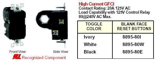
Well, it's not quite as I remembered, but here it is just the same:

donut20gfci.jpg
 
Last edited:
mdshunk said:
Yeah, let me dig it up. I posted about it years ago... hang on...

Well, it's not quite as I remembered, but here it is just the same:

donut20gfci.jpg
Thats a new one on me. There are so many devices made I don't think one person could possibly know of them all.
 
Am I wrong in thinking that what Franklin has suggested is above and beyond the code?

Under normal conditions with a good connection of the EGC at the pump, operation of branch circuit protection would work as usual. A fault to the pump casing would return to the transformer via the EGC. After 30 amps or so the 20 amp CB will eventually trip. Maybe. What they have done is add GF protection to ensure that when the EGC connection at the pump is corroded away and no longer continuous, the GF will interupt power to the pump at 10 ma current. Great idea.
 
Last edited:
ptonsparky said:
Am I wrong in thinking that what Franklin has suggested is above and beyond the code?

Under normal conditions with a good connection of the EGC at the pump, operation of branch circuit protection would work as usual. A fault to the pump casing would return to the transformer via the EGC. After 30 amps or so the 20 amp CB will eventually trip. Maybe. What they have done is add GF protection to ensure that when the EGC connection at the pump is corroded away and no longer continuous, the GF will interupt power to the pump at 10 ma current. Great idea.

Just the opposite; they are trying to DEFEAT the GFCI protection.

If the EGC does NOT go through the GFI, then a ground fault that is returned through the EGC will result in an unbalance of the UNGROUNDED conductors, which will trip the GFCI, as it is supposed to do.

But if the EGC is connected to the "load neutral" terminal of the GFCI breaker, then the breaker will sense that the loads are unbalanced with the difference returning through the pseudo-neutral EGC and will not trip the GFCI.

Connecting the EGC to the "load neutral" terminal of a 2-pole GFCI DEFEATS the function of the GFCI if the ground fault current is returned through the EGC.

Furthermore, if the GFCI breaker to the pump is a disconnect separate from the service panel (as they often are), then the disconnect is a subpanel and it is a violation of the code to connect the EGC to the neutral at a subpanel.
 
Since when do we ever run a submersible pump on a GFCI? What they are doing is detecting when the EG has come loose from the pump casing. When current is flowing normally the EG will pass current thru the GFCI. True, it will not trip while the EG is continuous, it isn't supposed to. Branch circuit protection should handle fault currents until the imbalance becomes excessive or the EG breaks. 10 ma is not much fault current and very likely will flow under normal operating conditons thru the EG. Remove the EG from the pump casing and now we have current imbalance on the GFCI thus detecting the broken EG. Normal branch circuit protection would not detect the loss of EG.
 
ptonsparky said:
When current is flowing normally the EG will pass current thru the GFCI. True, it will not trip while the EG is continuous, it isn't supposed to.
Tom, do you mean it isn't supposed to under this arrangement, or it isn't supposed to normally either?

10 ma is not much fault current and very likely will flow under normal operating conditons thru the EG.
I don't think this is true, under normal operating conditions. IMO, this would indicate a defective appliance.

Wouldn't that current flowing on the EGC under normal conditions constitute a violation of 250.6?
 
It isn't supposed to under this arrangement.

Many pieces of equipment have leakage current that is acceptable and will state it in the specs. How much current will flow through the EG on a normal 20 amp circuit breaker before it trips? We normally do not want to see 5 amps but the CB won't care.

This GFCI arrangement is not for personal protection. We will not come in contact with this pump while in operation. Go back to the OP. These are corrosive conditions and the pump must not be suspended on a metal pipe. The pipe would create a parrallel path for fault current & the GFCI protection would trip with acceptible levels of leakage even though the EG was continuous.

Depending on the conductivity of the water the GFCI may trip at 5 amps flow on the EG. Then again it may not.

A faulted pump with no EG is what causes the tingle in the shower with improperly bonded metallic sewer lines. Franklin is ensuring this does not happen by monitoring the EG.
 
Okay, I think I get where you're coming from now. :cool:

ptonsparky said:
Many pieces of equipment have leakage current that is acceptable and will state it in the specs.
Right - but if we do not involve the GFPE with the EGC, and then install GFPE that will trip at 10 mA, then this is accomplished. Monitoring the EGC isn't necessary - 10 mA is 10 mA, whether it's returning on the EGC or on the water.

Depending on the conductivity of the water the GFCI may trip at 5 amps flow on the EG.
Under the arrangement described, it becomes a lottery as to when (or if) the GFPE will trip. They seem to be unconcerned about any current flow on the EGC (since they're running it through the coil of current to be ignored).

A faulted pump with no EG is what causes the tingle in the shower with improperly bonded metallic sewer lines. Franklin is ensuring this does not happen by monitoring the EG.
1. What is proper for bonding of sewer lines? :)

2. Why is the setup described better at preventing a tingle than a typical GFPE setup?

(I'm not trying to pick on you, just visiting. :) )

Edit to add words and stuff.
 
:smile: Dang, you're going to make me work for this.

EGC is required by the NEC. Monitoring of its continuity is not. Plus for Franklin.

Pushing 10ma of current through an EG takes less potential than pushing 10ma through water of unknown conductivity. Motor insulation has definately broken down by then but not with a good EGC. Basically we don't care if 10 ma is flowing through an EGC, but we do care if it is flowing through the earth. Earth is not the intended return for fault clearing.

Properly bonded should be "unbonded". Use the same method as you would for other piping systems.

We won't have the tingle with a good EG connection, even with a faulted motor. Most of the current will return via EG. Remove the EG and you will.
 
Given my comment in the GFCI in Commercial Kitchen thread http://forums.mikeholt.com/showthread.php?t=86305 I find this set of manufacturer's instructions quite interesting.

Here we have a piece of equipment where code does not require ground fault protection, and where there is a chance of significant leakage current.

The manufacturer is suggesting using Ground Fault detection, but trying to selectively detect ground faults that are not returning on a known equipment grounding path. If the ground fault current returns on the EGC, then it doesn't trip the detector; if it returns on some other path, then it does trip the detector. This does seem like a clever approach to use available hardware to look for only _some_ ground faults.

I have to wonder if this is an accepted way of using such a ground fault detector, one that has been evaluated for sneaky failure modes by UL or some other group. Or is this someone's bright idea, not fully thought through?

For example, this setup would be sensitive to current flowing from the building grounding electrode system to the pump housing, which is also a grounding electrode. I could imagine nuisance tripping with _no_ leakage from the pump itself. Would the GFCI survive a nearby lightning strike, where there might be a large pulse of current down the EGC? Does the manufacturer have any standards for how much leakage current is permitted on the EGC, and would it be better to have a system which could test for that?

-Jon
 
Status
Not open for further replies.
Top