mstrlucky74
Senior Member
- Location
- NJ
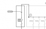
Looks like the diagram is calling for a bus tap (feeder tap, under NEC) to supply add-on section of gear, grounding included. What does the feeder schedule call for?Curious about the "grounding System" referred to in this note. So this work(in my view) is to add buss detail, lugs but the grounding part I'm not 100% about. Ground lugs to ground bar in the gear, I assume. Thanks.
Looks like the diagram is calling for a bus tap (feeder tap, under NEC) to supply add-on section of gear, grounding included. What does the feeder schedule call for?
So it's 4/0 from the grounding bus in the main gear to the grounding bus in the add-on gear. If run in wireway, one suffices. If you were to run in multiple conduits, you'd need one 4/0 in each conduit. If the drawing position is just esoteric, cut mating openings in gear sides, abut, install edge guard, and secure... not necessarily in that order.5 sets 4#400 & 4/0.
So it's 4/0 from the grounding bus in the main gear to the grounding bus in the add-on gear. If run in wireway, one suffices. If you were to run in multiple conduits, you'd need one 4/0 in each conduit. If the drawing position is just esoteric, cut mating openings in gear sides, abut, install edge guard, and secure... not necessarily in that order.
In many cases, the gear is ordered to match existing, and the entire side of existing is removed and busbars themselves are extended into new gear. Perhaps whoever engineered this could not find mating gear... or they simply didn't "engineer" the project.
In addition to what Rob said, the grounding in your diagram is GEC. The grounding you are asking about is EGC. This new gear is not service equipment as best I can tell from your description, so no GEC is necessary.But I'm thinking there needs to be a tie from the new gear to a ground bus separate of the gear. Kind of like this pic from another project.