PWDickerson
Senior Member
- Location
- Clinton, WA
- Occupation
- Solar Contractor
This is a weird one!
The installation:
Residential installation on a barn, 320A service, 120/240 split phase. Grid-tied PV, no batteries.
25 kva pad-mount utility xformer 110' from service equipment
Interconnect is line-side connection between meter and 200 amp main breaker in one of two main panels.
Conductors between interconnection point, fused disconnect, and production meter are #2 CU, about 10' in length total.
Conductors between AC combiner panel and fused disconnect are #1/0 AL, about 120' in length
We have two SMA SB7700US-TL-22 inverters adjacent to the AC combiner panel, combined AC max output is 64 amps, 15.36 kW
33 solar modules to inverter #1, 32 to inverter #2, 280-watt 60 cell modules, 5 strings of 11 and 1 string of 10
The system has been installed for about 10 weeks. Under high production conditions, the system generates a high pitched noise that is really obnoxious. This is not fan noise, it is an electronic noise generated at the interior of the inverters. When the inverters are making the noise, the same noise can also be heard at the service equipment and the utility transformer, though not as loud as at the inverters. The noise does not happen when the system is generating less than about 11-12 kW. When the noise happens, it comes on quickly and stays on. If either of the two inverters is turned off, the noise instantly goes away.
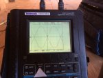
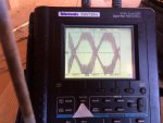
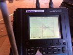
It sounded like high frequency harmonic distortion to me, so I borrowed an o-scope from a friend to check out the AC wave form. It is a 2-channel scope, so I was able to monitor both legs of AC power. I put the test leads at the bus in the AC combiner. The first photo is of the AC output waveform with only one inverter operating (no noise). Pics 2 and 3 are with the noise happening with both inverters running. The two photos are at 2 different time scales. It shows a wicked 5 khz harmonic on the primary 60 hz waveform. I would not have thought something like this was even possible. The peak-to-peak voltage of the harmonic is about 175 volts! Any ideas what might be causing this.
SMA tech support is scratching their heads. They initially thought might be an undersized utility transformer, but 25 kva should be adequate. They have sent us some data logging equipment so they can have something to analyze, but we have not received/installed it yet.
The installation:
Residential installation on a barn, 320A service, 120/240 split phase. Grid-tied PV, no batteries.
25 kva pad-mount utility xformer 110' from service equipment
Interconnect is line-side connection between meter and 200 amp main breaker in one of two main panels.
Conductors between interconnection point, fused disconnect, and production meter are #2 CU, about 10' in length total.
Conductors between AC combiner panel and fused disconnect are #1/0 AL, about 120' in length
We have two SMA SB7700US-TL-22 inverters adjacent to the AC combiner panel, combined AC max output is 64 amps, 15.36 kW
33 solar modules to inverter #1, 32 to inverter #2, 280-watt 60 cell modules, 5 strings of 11 and 1 string of 10
The system has been installed for about 10 weeks. Under high production conditions, the system generates a high pitched noise that is really obnoxious. This is not fan noise, it is an electronic noise generated at the interior of the inverters. When the inverters are making the noise, the same noise can also be heard at the service equipment and the utility transformer, though not as loud as at the inverters. The noise does not happen when the system is generating less than about 11-12 kW. When the noise happens, it comes on quickly and stays on. If either of the two inverters is turned off, the noise instantly goes away.
It sounded like high frequency harmonic distortion to me, so I borrowed an o-scope from a friend to check out the AC wave form. It is a 2-channel scope, so I was able to monitor both legs of AC power. I put the test leads at the bus in the AC combiner. The first photo is of the AC output waveform with only one inverter operating (no noise). Pics 2 and 3 are with the noise happening with both inverters running. The two photos are at 2 different time scales. It shows a wicked 5 khz harmonic on the primary 60 hz waveform. I would not have thought something like this was even possible. The peak-to-peak voltage of the harmonic is about 175 volts! Any ideas what might be causing this.
SMA tech support is scratching their heads. They initially thought might be an undersized utility transformer, but 25 kva should be adequate. They have sent us some data logging equipment so they can have something to analyze, but we have not received/installed it yet.