Help interpreting Main Panel Bus bar schematic?

Status
Not open for further replies.
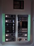
Based on the attached photo, Can anyone help me determine the number of possible double pole (240v) breaker positions?

I believe there are a total of four? As I see it there are Two (2) possibilities on each bar?

If I am correct, can they be identified by say ... 4+6 etc? If that is the way to help determine where they would be positioned, please provide the other combinations....? That would be a big help.

Thanks for any help.

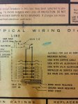
PS: and yes it is an older GE 100/125 Main.
 

Attachments

  • IMG_20170126_090306.jpg
    IMG_20170126_090306.jpg
    66.4 KB · Views: 1
1-3
7-9
11-13
15-17

2-4
8-10
12-14
16-18

The last three in each list would need to be a slim style or 1/2 size 2 pole.
 
I remain somewhat perplexed Here is what I have now.

I remain somewhat perplexed Here is what I have now.

1-3
7-9
11-13
15-17

2-4
8-10
12-14
16-18

The last three in each list would need to be a slim style or 1/2 size 2 pole.

OK perhaps I was not clear? I am looking for the ability to add another 240v Double Pole 20Amp Circuit Breaker, and looking for the proper location in the panel.

Currently, there are (2) 240V DP on the right side bus.... A 40A 240v for the electric range and a 50A 240v that feeds a subpanel under the main panel.

From what I know is the 40A Range uses pole 4+6.... The 50A seems to be using 14+16? But that does not make sense? (I would think it would be 12+14??)

On the left side bus - there is a 20A 240v DP breaker for the Air Conditioning. The AC uses poles 11+13.

I tried moving the range to 2+4 but only had 120Volts!

Now my best guess is that on the LEFT side bus I could install a 20A (slim 2pole - 240v) using 3+5 or 15+17?

Take a look at these pictures and compare the two photos and see if I am right?

14+16 still confounds me a bit - it should be 12+14.

Bear in mind... there are not bus lugs at every spot??
 

Attachments

  • IMG_20170126_105433.jpg
    IMG_20170126_105433.jpg
    132.7 KB · Views: 1
OK I will do that and post a new picture and we go from there?

OK I will do that and post a new picture and we go from there?

Re-number according to the panel nameplate and follow post #3 and see what you end up with. :)


Be right back...

OK I am back.... But At the panel I got corn-fused!
 
Last edited:
Be right back...
:lol:

Here. This might help clarify. The 40 Amp double pole breaker you have is the so-called 1/2 inch (or half size) breaker.

The schematic shows that the positions #2 & #4 as labeled on the schematic can only be the 1 inch of full size breaker. Placing the 40 Amp half sized double pole breaker, as you show in your photo, you will see, if you look closely at the bus bars under the breaker that there are NO small bus blades that line up with the 40 Amp breaker slots in jaws.

The top four bus poles are built only to accept full sized breakers (1"). The remaining lower bus poles can accept EITHER full or half size breakers. If you study the bus bar blades under the existing breakers, you will see what I am describing.

What this means is that the 40 Amp half size breaker in the position shown in your second photo is making a very bad connection and should absolutely not be put under load.
 
Not sure I understand yet?

Not sure I understand yet?

Re-number according to the panel nameplate and follow post #3 and see what you end up with. :)


What would be the next number if 1-3 includes 5-7? And 2-4 includes 6-8. (I need more drugs) LOL :blink:


#9 is a single pole 15 amp that powers the gas furnace fan .... 10 looks to be an open slot.

11 and 13 are for the 20amp AC 240v etc. WHAT AM I missing here?
 
WHAT AM I missing here?

What you are missing is the way the bus bar blades insert into the breakers. You have to look closely at that.

The upper part of the panel bus is different than the lower part of the bus
 
OK so where Can I move the 40Amp?

OK so where Can I move the 40Amp?

:lol:

Here. This might help clarify. The 40 Amp double pole breaker you have is the so-called 1/2 inch (or half size) breaker.

The schematic shows that the positions #2 & #4 as labeled on the schematic can only be the 1 inch of full size breaker. Placing the 40 Amp half sized double pole breaker, as you show in your photo, you will see, if you look closely at the bus bars under the breaker that there are NO small bus blades that line up with the 40 Amp breaker slots in jaws.

The top four bus poles are built only to accept full sized breakers (1"). The remaining lower bus poles can accept EITHER full or half size breakers. If you study the bus bar blades under the existing breakers, you will see what I am describing.

What this means is that the 40 Amp half size breaker in the position shown in your second photo is making a very bad connection and should absolutely not be put under load.


OK so where Can I move the 40Amp? I know what you mean about the lack of Small Bus Tabs. Is there somewhere on that right side bus for another double pole slim that will be correct for the load?

Would a full size (1-inch 40 Amp) work in the top at #2?
 
Be right back...

OK I am back.... But At the panel I got corn-fused!
If you number the slots to match the printed diagram, you will see that there are three places on each side that you can put a double pole full sized breaker. There are also several places on each side where you could put a handle tied pair of half size breakers to get two phases. The top two half size on the right column (with a blank above them) are an example of this in terms of alignment, but will not actually work properly since they are in a position that only accepts full sized breakers.
But what you label as 11-13 on the left are correctly placed for a 240 or 120-0-120 MWBC circuit.

If quad breakers (four half width) are made for this panel, using the inner pair and the outer pair of each and locating them correctly will allow you to get two double pole circuits in the space of one full sized DP breaker.
Quads are usually available in several combinations of handle tie with or without common trip. Read the specs carefully.
 
Last edited:
But the handle tied pair in what you number as 14-16 are actually both on the same phase. This cannot be used for an MWBC since the neutral current will be doubled.
What you label as 11-13 on the left are correctly placed for a 240 or 120-0-120 MWBC circuit.

Edit: to add: GoldDigger, this is a great catch. I initially missed it. It raises alarm bells for me. Thanks.

Richman, Respectfully, I think you are out of your depth, with this and you need an electrician to come to your house.
 
Last edited:
If you number the slots to match the printed diagram, you will see that there are three places on each side that you can put a double pole full sized breaker. There are also several places on each side where you could put a handle tied pair of half size breakers to get two phases. The top two half size on the right column (with a blank above them) are an example of this.
But the handle tied pair in what you number as 14-16 are actually both on the same phase. This cannot be used for an MWBC since the neutral current will be doubled.
What you label as 11-13 on the left are correctly placed for a 240 or 120-0-120 MWBC circuit.

If quad breakers (four half width) are made for this panel, using the inner pair and the outer pair of each and locating them correctly will allow you to get two double pole circuits in the space of one full sized DP breaker.
Quads are usually available in several combinations of handle tie with or without common trip. Read the specs carefully.

Is it possible for you to draw me a picture of what you mean? I thought I had the panel labeled right but evidently not.
 
Richman,

Even though you have 50 years in the construction industry, it appears to me that your electrical experience is weak enough that trying to help you over the internet is extremely dangerous.
I would recommend that you get licensed electrician to come on site to do the work for you.
 
Respectfully, I think you are out of your depth, with this and you need an electrician to come to your house.

I agree I need bit more help. I know 11&13 are correct, I want to have the other side be correct. Would a single full size 40 amp for the range be the correct 240v breaker in slot 2-4?

the
correct
position
for the
50 amp breaker should be 12-14 right?

I just want this to be safe until the electrician can get here.
 
I am closing this thread in accordance with forum rules.

This site is designed for:

Contractors
Electricians
Engineers
Inspectors
Instructors
Other electrically related individuals
This Forum is for those in the electrical and related industries.

Questions posted that appear to be an attempt to gain assistance with an electrical installation will be removed. Forum rules prohibit us from assisting a person to perform or assist others to do electrical work who are not qualified. Mike Holt Enterprises and the Moderators of this Forum do not wish to place you and your family in danger, by allowing others to give you too little information to ensure that the installation is safe
 
I agree, it's time to close it. I allowed this thread because the question was just about panel space. It is obvious now that the op wants to do the work himself..
 
Udate

Udate

A PM from al hildenbrand informed me that he and the OP were able to meet up and resolve the issue with the breaker. The Forum's members' responses to the OPs questions had impressed upon him the need for professional help and he was extremely appreciative of the way this all unfolded, and resolved.
 
Status
Not open for further replies.
Top