Help with backfeeding single phase transfromers

Status
Not open for further replies.

iamsam

Member
Location
Austin, TX, USA
Background info:
We are in the process of rewiring a transformer that will be backfed for experimental work here at the office. I was initially tasked with providing a variable voltage system from 0-8000VAC. The setup was a 14kVa variac capable of 0-280VAC coupled with a backfed pole mount transformer(see below nameplate).
Pole_Plate.jpg

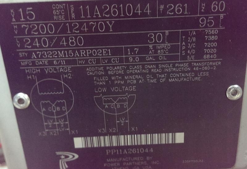
The two hot lines out of the variac were wired across x1 and x3, with x2 left floating. This system worked as intended with no issues and we were able to use a full 40A(measured on the LV side) @ 8kV without issue.
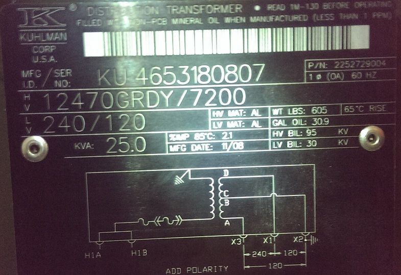
After some testing it was discovered that our initial data was not correct, and we would need upwards of 12kV to continue. On a budget, and not wanting to purchase a new variac to feed the pole transformer 480/redo the breaker and disconnect done by the electrician, we purchased a surplus pad mount tranformer(see below nameplate).
Pad_Plate.jpg

Current Problem:
There was a learning curve when the new transformer showed up, as no one here has any experience with distribution transformers(I'm hoping the mistake/fault lays somewhere here). I learned about, then purchased, loadbreak elbows, a bayonet fuse, and rented a crimper to get it wired up. Once wired up in the same way as the previous unit (voltage accross x1 and x3, with the grounding strap to x2 removed) we get nothing. When an oscilloscope probes the output side the high voltage is present, but placing a load across it yields nothing. The only conclusion we could draw from that is we are picking up the noise from the coils.
I would love to get some input on anything that could be causing this behavior. One thing is that the diagram shows a fuse inline with a fuse in a holder, but I could only find the place for the bayonet fuse.
Thanks, Sam
 
Disconnect everything and check for continuity between high voltage bushings and the primary grounded conductor connection point.
 
You do understand, I hope, just how dangerous, actually DEADLY, even a tiny amount of 12kV is going to be, right? The switchgear to handle that much voltage safely is HUGE and expensive, mostly because of how things tend to explode violently if anything should go wrong. This is not something to be trifled with, experimental or not. Yes the transformer is small which limits the energy, but the issue is that at 12kV you don't have to touch anything to get killed, it searches you out and kills you just for being in the vicinity. The comment on using oscilloscope probes is the thing that has me worried; the proper device for measuring 12kV is a probe at the end of a 10 ft. pole, LITERALLY.
 
And that probe will be a very specialized HV probe too!

Under just the right (wrong!) circumstances .5VA can kill a person. 15kVA leaves a lot of room for unlikely things to be sure to happen.
 
Last edited:
Don, thanks for the suggestion; we checked it out and I will recheck tomorrow when back in the office.
Also, this is not a backyard project. We are very aware of the dangers of high voltage. When the system is live we are standing 10 feet away from the transformer/HV apparatus, with only 2 guys in the area(one at the control panel and one standing with his hand on the 240V disconnect feeding the whole thing). We are an engineering firm, generally dealing in the enterprise electronics space, and were asked to validate a result that came out of a university lab. I am a mechanical engineer and am working along side an electrical engineer on this project. This is not our normal role within the company; the electrical engineer does our printed circuit boards(DC and signal circuits) and I design enclosures for products like servers. I would happily bring in an electrician to come and take a look, unfortunately you can guess the reactions of the ones we have contacted! Hence, its my problem to figure out.
P.S. we are using probes for the scope that are designed for high voltages.
 
Last edited:
How do you plan on getting higher voltage in your setup when both transformers have the _same_ rated high voltage?

You have changed from a transformer rated 240/480 on the LV side to one rated 120/240 on the LV side...but you cannot operate a transformer in excess of its rated 'volts per turn' or the core will saturate.

I second Jraef's concerns.

-Jon
 
Checked for continuity, everything is as it should be. Our problem is that the pad mount transformer does nothing when fed voltage. I may have to scrap/sell off the pad mount and look for another transformer all together. I was hoping to avoid that because this will set the project back another week at best.
Thanks
Did you try a simple ohmmeter test on the disconnected HV and LV windings? It could be something as simple as an internal fusible link opening up, although I am not sure how you would fix that. Or an internal short, of course, if it pulls high input current and still delivers no output voltage.
 
What kind of load are you going to supply. If the load is minimal enough consider an ignition transformer or neon sign transformer maybe, or even a fence charger.
 
Checked for continuity, everything is as it should be. Our problem is that the pad mount transformer does nothing when fed voltage. I may have to scrap/sell off the pad mount and look for another transformer all together. I was hoping to avoid that because this will set the project back another week at best.
Thanks

Something is not adding up???

you stated that you fed the variac into the first transformers on the X3 and X1 bushings, with a 0-280vac variac you should have never saw 8kv out as those are the 480 volt bushings??, only if you fed in through the X3 X2 or X1 X2 bushings would you seen the full output voltage, with 280 going in on the X3 and X1 bushings I would only expect 4.2kv out not 8kv.

If you are doing the same mistake on the bushings on the new transformer you would be sending in the 240 volts on the 120 volt bushings and you are saturating the LV windings, which is why your not getting an output???

I would double check which bushings your connecting to?

Also as said above the only differance between the two transformers except one is aluminum windings and one is copper, is the fact that only the LV side is differant, both have a 7.2kv high side, but the first one is a 240/480v and the second one is a 120/240v so I don't see how you are going to get 12kv out of it, again if you put 240 into the 120 volt windings it will only over saturate the windings and you won't get an output, you need a transformer with a 12kv primary, the 12.4kv on the lable only means it is rated to be a part of a 12.4kv/7.2kv WYE bank when wired in a WYE with three phases, but the windings are only 7.2kv.

lower the voltage to 120 from the variac and you should see 7200 out of it if as I suspect you connected to the X1 and X2 bushings????
 
Last edited:
The LV diagram shows that you can put the first transformer LV windings in series or parallel it comes with it connected in series A-X3 C+B-X2 and D-X1, the optional LV diagram shows that the two 240 volt windings are in parallel, A+C-X2 and B+D-X1 you might want to take a look and make sure which way it is connected, this might be a internal connection.

The second transformer shows the LV windings in series, A-X3 C+B-X2 and D-X1, I would double check and make sure this is so, if C&B are not connected you will not get an output?


If you figure out the problem with the second transformer you could series the primary of the first transformer with the primary of the second transformer but because of the grounded primary on the second transformer it can only be done by connecting the H2 from the first transformer to the H1 of the second transformer, and connecting the load between the H1 of the first transformer and the grounded connection on the second transformer, this will produce 14.4kv with 240 volts input on both transformers, so 200 volts input will give you 6kv out of each or 12kv with the primaries in series.

As others have said, 12kv can jump quit far so I would have your O-scope probe on the end of a 10' fiberglass non-conductive pole no way would I get near it.
 
Status
Not open for further replies.
Top