High Leg Load Calculations

Status
Not open for further replies.

steve66

Senior Member
Location
Illinois
Occupation
Engineer
How does everyone do load calculations for a 240V high leg service?

I divide the loads up per phase. All the 120V loads go on phase A. Then I put the 240V line-line loads on phases B and C. (For example, a 240V single phase air conditioner at 13 amps would be 3120VA on phase B. If I have 2 of these AC's, I would put the other one on phase C.)

Then I add up the KVA on each phase and divide by 240 volts to get the phase currents. To get the line currents, I take the square root of the sum of the squares of phase A and phase B currents.

For example, assume there is 48KVA on phase A, 24KVA on phase B, and 20KVA on phase C. To find the largest line current, I would take the 48KVA and the 24KVA to get 200A and 100A. Then sqrt(200^2+100^2) = 223 amps.

So in theory, this load could be ran from a 225A feeder. Does all that sound correct, or does anyone see any errors in my calculations?

Thanks:
Steve
 
steve66 said:
How does everyone do load calculations for a 240V high leg service?

I divide the loads up per phase. All the 120V loads go on phase A. Then I put the 240V line-line loads on phases B and C. (For example, a 240V single phase air conditioner at 13 amps would be 3120VA on phase B. If I have 2 of these AC's, I would put the other one on phase C.)

Thanks:
Steve
If you assume C is the hi leg, then the 120 volt and the 240 volt single phase
is connected to A,B and Neutral. The 3 phase loads are connected to A,B and C.
 
steve66 said:
For example, a 240V single phase air conditioner at 13 amps would be 3120VA on phase B.

You can not put your load on a single conductor and call it a phase. Voltage requires two points, so your 240V load is connected to line B and ??? The result is 13A on line B and 13A on line???

So if your first A/C is connected to line B and C then you will have 13A on both conductors and your second A/C load is on C and A then the result is 13A on line A, 26A on line B, and 13A on line C (or 3120VA on B and C, and 3120VA on C and A).

Why do you calculate all of your 120V loads between line A and neutral? Do you just do this for a fudge factor during calculations?
 
jim dungar said:
Why do you calculate all of your 120V loads between line A and neutral? Do you just do this for a fudge factor during calculations?

I think it is because of the way the transformer station secondary is connected delta (grounded). If you draw out a picture of a three phase transformer station with the secondary terminals (I am thinking overhead station with 3 single phase transformers), there is only one transformer winding that will produce 120 V because it is the only one center tap-grounded. At least that is how I would do it sizing transformers, but if you are sizing a feeder, then putting all single phase loads on one phase does not make sense to me, although it will work and give you some extra cushion.

And Jim, while I agree that "it takes two," wouldn't there be a vector addition of the currents from the loads on A,C and the loads on B,C giving a higher kVA on phase B, than on phases A and C?
 
wirenut1980 said:
I think it is because of the way the transformer station secondary is connected delta (grounded). If you draw out a picture of a three phase transformer station with the secondary terminals (I am thinking overhead station with 3 single phase transformers), there is only one transformer winding that will produce 120 V because it is the only one center tap-grounded. At least that is how I would do it sizing transformers, but if you are sizing a feeder, then putting all single phase loads on one phase does not make sense to me, although it will work and give you some extra cushion.

And Jim, while I agree that "it takes two," wouldn't there be a vector addition of the currents from the loads on A,C and the loads on B,C giving a higher kVA on phase B, than on phases A and C?


There are (2) sets of 120V circuits. Line A to neutral and Line C to neutral.
Yes there are vector additions that need to be taken into account but it is common to ignore them for illustration as well as estimating purposes.

My real point is that there is no such thing as "Phase A". The term phase (as in three phase system) refers to a line-line voltage. Voltage requires two reference points so a load is connect to L1 & L2 or L1 & N never to simply A. This means that current is not on a "phase" either it must always flow "in on one conductor and out on another". I know that our industry regularly talks about a single conductor as a "phase", but I feel most mis-understandings occur when people confuse the term "phase conductor " for the less confusing(?) term "line conductor".
 
It looks like I need to define the terminology I am using. This is what I was thinking of when I said I put single phase loads on "phase A". Wirenut has the basic idea. I was basically considering "phase A" to be one of the transformer windings.

3PHASE.jpg


The basic thing I am trying to find out is how do you calculate the largest line current? Since the loads are tied in a delta arrangement, the load currents aren't the same as the line currents. However, I usually start by finding the total load currents first. (i.e. the current from Line A to Line B, the current from Line B to Line C, etc.).

Steve
 
Are these services still being installed?

I almost never run into them and have never seen a new installation of one in this area.

Our choices are

480Y/277

208Y/120

120/208 single phase (usually in a city for small services)

120/240
 
steve66 said:
The basic thing I am trying to find out is how do you calculate the largest line current? Since the loads are tied in a delta arrangement, the load currents aren't the same as the line currents. However, I usually start by finding the total load currents first. (i.e. the current from Line A to Line B, the current from Line B to Line C, etc.).

Steve
Steve when ever I have seen a system as discribed it comprised of three single phase transformers as a transformer bank. The three wire trans is sized for the lighting load + the power load the other two two wire transformers would be smaller to carry just the power load.
Does this help??
 
Last edited:
Steve, a 240/120v Delta, open or closed, is identical to a 240/120v single-phase service (such as in a residence), plus the high leg, which is useful only for line-to-line loads. Ignore the high leg for 120v loads, and connect them as in a 240/120v, 1-phase system.

In other words, divide the 120v loads between A and C phases, as you would in a residence, and save the high leg for only 3-phase and 1-phase, 240v loads. The latter may be connected between any two phases, A-B, A-C or B-C, but try to balance out the heavy A- and C-phase 120v loads.

Your diagram shows a closed Delta, which is better than open. Connecting a large single phase load across the open side of an open Delta does introduce a bit of instability, since the source impedance is a bit higher than it would be across a real secondary.
 
Bob:

I generally run into high leg deltas at existing services. If I am looking at them, it is normally because we are adding new loads, or considering upping the service size. (I recently ran into one that has been installed for a new building within the last 10 years).

So basically I'm trying to calculate the service size required given all the loads. I just wanted to be sure my math is correct.

Cpal: Yes, they are normally three single phase transformers. But I don't have to worry about that for the service size. I only have to size the service starting at the service entrance conductors, and I'll let the utility worry about sizing the transformers.

Larry: I'm not really sure if they are open or closed deltas. I'm guessing that's more concern to the POCO than to me. (Although how to do fault calcs on these could be another thread I would be interested in!)
 
steve66 said:
The basic thing I am trying to find out is how do you calculate the largest line current?
First let's call your line currents L1, L2 , and L3, respective to Line A, Line B, and Line C of your diagram. Additionally, let's call your VA loads a, b, and c for "Phase A", "Phase B", and "Phase C" loads respectively. To determine the largest line current, compare:
L1 = √(a^2 + c^2 + ac) ? V
L2 = √(a^2 + b^2 + ab) ? V
L3 = √(b^2 + c^2 + bc) ? V
...where V is line to line voltage.​
A unity power factor is assumed, as is a balanced line to neutral loading. The formulas are mathematical shortcuts for determining magnitude by vectorial addition.

For your example:
Line A (L1) = 252.21A
Line B (L2) = 264.58A
Line C (L3) = 158.99A​
 
Thanks Smart. So I was basically forgetting to add the last term, (ac for example).

I have seen those equations posted here before, and someone once asked for a proof. I can't figure out how to prove them, but they look so familiar I am sure they are one of the basic laws that has a name. (It's not the "law of cosines", but its close. I think it is one of the vector math definitions, like "dot product", or something else.) Anyhow, I'm sure one of these days I'll figure it out.

Until then I thought I would do a quick check on your formula. (Not a proof, but a quick "maybe its right" or its "definately wrong" check.) We know that for a balanced delta, the line currents are just sqrt(3) times the phase currents. So what happens if we use your formula with a=b=c?

Taking the first equation, we can subsitute a for c (since a=c). Then:

L1=sqrt(a^2 + a^2 + a*a) = sqrt(3 * a^2) = sqrt(3) * sqrt(a^2)

which gives:

sqrt(3) * a

So your equation at least works for balanced currents. And it shows us exactly where the magic number sqrt(3) comes from!!!

I think that's pretty neat:smile:

Steve
 
steve66 said:
I have seen those equations posted here before, and someone once asked for a proof. I can't figure out how to prove them, but they look so familiar I am sure they are one of the basic laws that has a name. (It's not the "law of cosines", but its close. I think it is one of the vector math definitions, like "dot product", or something else.) Anyhow, I'm sure one of these days I'll figure it out.
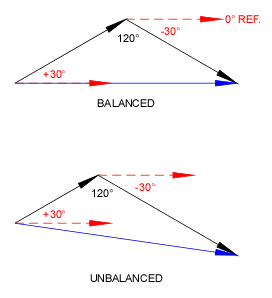
Actually, it is the Law of Cosines. The L-L voltages and currents at unity power factor are + and - 30? relative to the line's reference angle. When drawn as vectors and added (latter's tail to former's arrow), the angle between them is always 120?.
calc1.gif

Using one the of Law of Cosines formulas...
c^2 = a^2 + b^2 ? 2ab cos θ
...and cos 120? = ?0.5 we get...
c^2 = a^2 + b^2 + ab
 
Smart $ said:
L1 = √(a^2 + c^2 + ac) ? V
L2 = √(a^2 + b^2 + ab) ? V
L3 = √(b^2 + c^2 + bc) ? V
...where V is line to line voltage.​

Have patience because I am old and still trying to learn plus I don't even know if I will get the question stated correctly.

V for L1 would be voltage of a to c, V for L2 would be voltage of a to b, etc?
Under ideal conditions 240v for each. Real world I may have 235, 242, 248.
Can this be used to predict current imbalance on phases for normally balanced load, ie a single three phase motor?
 
ptonsparky said:
Can this be used to predict current imbalance on phases for normally balanced load, ie a single three phase motor?
I'm not only less than certain, I am less than uncertain :D

Without a comprehensive understanding of the effects of unbalanced voltage on induction motors, I am quite hesitant to even speculate.
 
Status
Not open for further replies.
Top